AMAZON multi-meters discounts AMAZON oscilloscope discounts
OBJECTIVES
• state three reasons why speed controllers are used with wound-rotor induction motors.
• list and describe the physical construction of two basic types of manual speed controllers.
• explain the operation of a faceplate controller with a protective starting device.
• explain the operation of a drum controller.
• summarize the National Electrical Code regulations regarding the wire size for the stator circuit, the wire size for the rotor circuit, starting overload protection, and running overload protection.
• draw wiring diagrams for wound rotor motor control.
Manual speed controls for wound rotor motors are quickly becoming obsolete. How ever, the maintenance electrician still needs a working knowledge of the operations of this type of control.
Many industrial applications require the use of wound-rotor induction motors with speed controllers. This unit covers the details of the operation of manual speed controllers and their connection to wound-rotor motors. Information on National Electrical Code regulations which apply to wound-rotor induction motor installations also is presented.
Reasons for Use of Speed Controllers
Speed controllers are used with wound-rotor induction motors for three basic reasons:
• to limit the starting surge of current to the motor by inserting resistance in the rotor circuit.
• to improve the starting torque of a wound-rotor induction motor by inserting resistance in the rotor circuit.
• to control the speed of a wound-rotor induction motor by varying the resistance in the rotor circuit.
FACEPLATE CONTROLLER
The simplest form of manual speed controller is the faceplate controller ( 1). In this type of controller, three sets of contact buttons are mounted on a panel. Each set of contact buttons is connected to a separate tapped resistor housed in the speed controller box. The resistance value of each resistor section is varied by a contact arm. For the faceplate controller illustrated in 1, note that the three contact arms are connected at a common point at the center. A handle attached to one of the arms moves all arms simultaneously. These arms are spaced 120 mechanical degrees apart so that equal amounts of resistance can be cut in or out of each tapped resistor. This faceplate manual speed controller is connected in a three-phase wye arrangement.
ill 2 shows the connections between a faceplate speed controller and a wound-rotor induction motor. As the three-phase, wound-rotor motor is started, all of the resistance in the speed controller is inserted in the rotor circuit. The stator circuit's connected across the three-phase line voltage by an across-the-line motor starter switch con trolled from a pushbutton station. Because the maximum value of resistance is inserted in the rotor circuit at startup, the starting surge of current is limited. As a result, the starting torque is improved. After the motor has started, resistance is cut out of the rotor circuit using the speed controller until the desired speed is obtained.
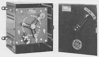
ill. 1 Speed regulating rheostat with auxiliary control switch
for interlocking with or controlling operation of a magnetic line switch.
Faceplate Controller with Protective Starting Device
If a wound-rotor induction motor is started with all of the speed controller resistance cut out of the rotor circuit, the starting surge of current to the stator windings will be high and the starting torque developed by the motor will be poor.
A protective starting device is used with a faceplate controller to insure that the motor is started with all of the resistance inserted ( 3). The motor can be started only when the arms of this special type of controller are in the slow position with all of the resistance inserted in the rotor circuit.
A speed controller of this type has a pair of contacts which are closed when the three movable arms of the controller are in the slow position. These contacts are in series with the normally open start pushbutton. When the start pushbutton is pressed, the coil of the magnetic across-the-line starter switch is energized. The starter contacts close and the rated three-phase line voltage is applied to the stator windings. As the motor accelerates, the movable arms of the speed controller can be adjusted to obtain the desired speed. As the arms are moved from the slow position, the faceplate controller circuit contacts open. However, the contacts of the across-the-line magnetic motor switch are closed. Since one pair of these contacts acts as a sealing circuit around the normally open pushbutton and the open contacts of the circuit on the faceplate controller, the main starter coil remains energized and the motor continues to operate.
The motor cannot be started if the speed controller isn't in the slow position. This is due to the fact that the control circuit to the coil of the magnetic motor switch is open because the contacts of the faceplate controller are open. Therefore, the motor switch won't operate when the start pushbutton is closed. To start the motor, the adjustable arms of the faceplate controller must be in the start position.
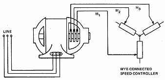
ill. 2 Connections of a faceplate speed controller to a wound-rotor
motor
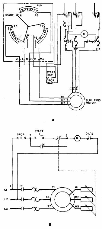
ill. 3 Faceplate controller with a protective starting device
A) Wiring diagram of a manual speed regulator interlocked with a magnetic
starter B) Elementary diagram of figure 3A
DRUM CONTROLLER
The drum controller, figure 4, is another type of manual speed controller which can be used with wound-rotor induction motors.
A drum controller consists basically of a case, contact fingers, the cylinder assembly, and external resistors. The case consists of a back piece and end pieces made of plate metal and a cover made of sheet metal. The cover fits over the end pieces and is removed when maintenance or repair work is required. The cover may be provided with a rubber gasket to make it dustproof. The wiring is brought to the controller through bushed holes or condulet fittings either in the back plate or the bottom end piece of the case.
The contact fingers of the drum controller are stationary contacts. The three wires from the rotor slip rings are connected to these contacts, as are the wires from the externally mounted grid resistors. Each contact finger is made of brass or steel and has a copper tip. Each finger is mounted and pivoted so that adjustments can be made on a spring to obtain the proper contact tension.
A drum controller also contains a vertical cylinder mounted on an insulated shaft. This cylinder provides the moving contacts that make and break connections to the various fixed contact fingers. The contacts on the cylinder are made of rolled copper segments which are moved by a handle located at the top of the speed controller.
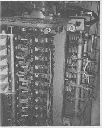
ill. 4 Drum controller used for control of a wound rotor motor
The controller resistors usually are mounted outside and behind the controller case. The resistor units are cast from iron or a metal alloy, figure 5. Connecting wires from taps on the resistors terminate at contact fingers in the drum controller.
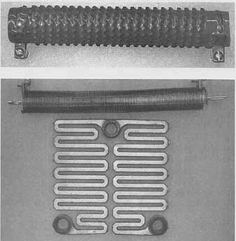
ill. 5 Resistors that may be used In wound rotor motor control
Operation of a Drum Controller
When the controller handle is in the slow position, the maximum resistance of the controller is inserted in the three phases of the rotor circuit. (The resistors of the speed controller are connected in wye.) As the controller handle is moved toward the run position, the copper contacts on the cylinder assembly make contact with various stationary fingers and sections of the resistance are cut out of the rotor circuit. When the handle is in the run position, all of the resistance of the speed controller is cut out of the rotor circuit. As a result, the motor operates at its rated speed.
ill 6 is a diagram of the internal connections of a drum-type manual speed controller. This circuit indicates that in the run position, the leads from the rotor slip rings. are connected together and the resistance of the controller is cut out of the rotor circuit.
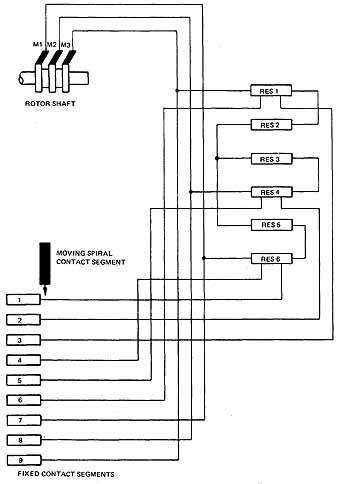
ill. 6 Connections of a drum-type manual controller
The stator circuit's connected directly across the three-phase line by an across- the-line motor switch controlled from a pushbutton station. Some drum controllers may have a small pair of main relay coil contacts which are closed only when the speed controller is in the start position. These contacts are in series with the normally open start pushbutton. If an attempt is made to start the motor with the speed controller handle not in the slow position, the motor won't start. If the speed controller handle is returned to the slow position and the start pushbutton pressed, the motor will accelerate slowly. The operator can then adjust the speed of the motor to the desired value. After the motor has started, the coil contacts and the normally open start pushbutton is shunted out by the sealing contactors in the magnetic motor switch.
NATIONAL ELECTRICAL CODE REGULATIONS
The National Electrical Code in Section 430-2 3 requires for continuous duty that the conductors from the rotor slip rings to the speed controller have an ampacity (current-carrying capacity) not less than 125 percent of the full-load current rating of the rotor, secondary circuit.
Resistor Duty Classification |
Ampacity of Wire in Percent of Full-load Rotor Current |
Light starting Heavy starting Extra heavy starting Light intermittent Medium intermittent Heavy intermittent Continuous |
35 45 55 65 75 85 110 |
The Code lists several special industrial applications where the resistors are separate from the controller for which percentage values of the full load current other than 125 per cent are allowed for the determination of wire size (the conductors connecting the controller to the resistors). As in the previous paragraph, for motors used in special industrial applications, the Code permits the application of other percentage values to the full-load-current rating of the rotor to determine the rotor circuit wire size.
If the speed controller resistors are separated from the speed controller, conductors are required to feed from the connection points on the resistors to the contact fingers. The Code also gives specific information on the percentage values full-load current to be used to determine the size of these conductors.
The fusible starting protection for a wound-rotor induction motor is to be not more than 150 percent of the full-load motor current rating (NEC Table 430-152). This starting protection usually consists of fuses located in the motor disconnect switch. Wire ampacity is no less than 125 percent of the motor full load current (NEC Section 430-22).
Running overload protection is to be provided for wound-rotor induction motors. For a motor rated at more than one hp and marked to have a temperature rise of not more than 40 degrees Celsius, the running overload protection shall be rated at not more than 125 per cent of the motor full-load current rating [ Section 430-32(a)]. The running overload protection usually consists of thermal overload units located in the magnetic motor starter. The Code also states that the secondary circuits of wound-rotor induction motors, including conductors, controller, and resistors, shall be considered to be protected by the running overload devices provided in the primary circuit. [ NEC Section 430-32(d).]
The phrase primary circuit, when referring to wound-rotor induction motors, means the stator winding. The phrase secondary circuit, as applied to wound-rotor induction motors, means the rotor circuit.
TERMINAL MARKINGS
The stator leads of a, three-phase, wound-rotor induction motor are marked T1, T2 and T3. Note that this is the marking system used with three-phase, squirrel-cage induction motors.
The rotor leads of a wound-rotor motor are marked M1, M2 and M3. The M1 lead connects to the slip ring nearest the bearing housing, lead M2 connects to the middle slip ring, and lead M3 connects to the slip ring nearest the rotor windings.
SUMMARY
Manual speed controllers are still in operation because of their ruggedness and reliability. The concept of manually controlling the wound-rotor motor is to control the primary (stator) circuit and to control the resistance of the secondary (rotor) circuit. It is important to be able to understand basic control philosophy and to read diverse control schemes. A working knowledge of the wound-rotor motor principle helps in all types of motor theory and control system troubleshooting.
REVIEW / QUIZ:
A. Give complete answers to the following questions.
1. Give three reasons why speed controllers are used with wound-rotor induction motors.
2. List the two basic types of manual speed controllers used with wound-rotor induction motors.
3. A 230-volt, three-phase, 10-horsepower wound-rotor induction motor has a full-load stator current rating of 28 amperes and a full-load rotor current rating of 40 amperes per terminal. Determine the fuse size required for starting overload protection for this induction motor. ____
4. Determine the size of the thermal overload units required for the induction motor given in question 2. ______
5. What size wire, Type THBN, should be used for the stator circuit of the motor given in question 2?
6. What size wire, Type THHN, should be used for the connections between the slip rings and the speed controller for the motor in question 3? _____
7. What size wire, Type THHN, should be used between the external resistors and the speed controller in the motor in question 3 if the duty classification is “Light Intermittent Duty”? Check the Code before answering this problem.
8. Draw the wiring connection diagram of a wound-rotor induction motor which is started by means of an across-the-line magnetic motor starter switch controlled from a pushbutton station. Include a wye-connected speed controller in the rotor circuit.
9. What precaution is provided on some speed controllers to prevent the starting of the motor when the speed controller is left in the run position?
B. Select the correct answer for each of the following statements and place the corresponding letter in the space provided.
10. What type of speed controller is used with a wound-rotor motor?
a. Primary resistor c. Autotransformer b. Secondary resistor d. Reactor
11. When starting a wound-rotor motor, full resistance is inserted in the secondary circuit and a magnetic starter applies full line voltage to ...
a. the stator windings. c. the starting resistors.
b. the slip wings. d. the primary resistors.
12. The rotor winding leads of a wound-rotor motor are brought out to
a. two slip rings. c. four slip rings.
b. three slip rings. d. a centrifugal switch.
13. The stator circuit of a wound-rotor motor is sometimes called the ...
a. primary circuit. c. rotor.
b. secondary circuit. d. frame.
14. The terminal lead connected to the slip ring nearest the bearing housing is
a. T1 c. M3
b.T3 d.M1
15. A drum controller is used for ...
a. reversing the stator.
b. switching resistances in the secondary.
c. braking.
d. reversing the rotor.
16. For best starting results, apply ...
a. minimum voltage to the stator, with maximum resistance in the rotor.
b. full voltage to the stator, with maximum resistance in the rotor.
c. full voltage to the rotor, with maximum resistance in the stator.
d. full voltage to the stator, with minimum resistance in the rotor.