AMAZON multi-meters discounts AMAZON oscilloscope discounts
OBJECTIVES
• state the differences between a shunt generator and a compound-wound generator.
• define what is meant by a cumulative compound-wound generator and a differential compound-wound generator.
• describe how the voltage regulation of a generator is improved by compound windings.
• list changes in output voltage at full load due to the effects of over-compounding, flat compounding, under-compounding, and differential compounding.
• draw the basic generator circuit.
• connect the generator.
The voltage regulation of a generator is an important factor in deciding the type of load to which the generator should be connected. For lighting loads, a constant terminal voltage should be maintained when the load current increases. A simple shunt generator can only do this if expensive regulating equipment is also used.
Generators designed to maintain a constant voltage within reasonable load limits may have a double winding in the field circuit. The second winding is wound on top of, or adjacent to, the main winding. This second winding is called the series winding to distinguish it from the main shunt winding. The series winding has fewer turns than the shunt winding. Since the series winding is connected in series with the armature and load, it carries the full-load current, and is heavier gauge wire than the shunt field. A generator with such a double-field winding is called a compound-wound generator.
ill 4 shows the basic circuits of two ways to connect a compound-wound generator: the long shunt and the short shunt. In the short shunt circuit (A), the main shunt field is connected directly across the brushes; in the long shunt circuit (B), the shunt field is connected across the combination of the armature and the series field. The operating characteristics of these circuits are quite similar, but the short shunt is preferred because the shunt field remains more constant and isn't affected by changes caused by the series field.
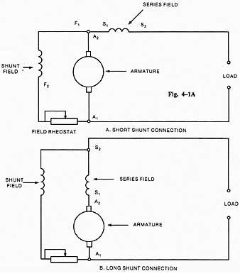
Ill. 1A Short shunt compound generator connection. A. SHORT
SHUNT CONNECTION; SHUNT FIELD; SERIES FIELD; FIELD RHEOSTAT. Ill. 1B
Long shunt compound generator connection: B. LONG SHUNT CONNECTION
COMPOUND FIELD WINDINGS
Two important details of the compound-wound generator must be considered: (1) the relative direction of the currents through both windings of a particular field pole, and (2) the magnetic effects which these currents can produce.
The series and shunt windings of a single pole of a compound-wound generator are shown in, figure 2. Winding (A) is the series winding through which the load current passes; winding (B) is the normal shunt winding. If the load current is in the direction illustrated in 2, the magnetizing force of the series winding (A) will aid the shunt winding (B) and increase the strength of the magnetic field. The current in the shunt winding isn't normally strong enough to saturate the core. If the load current through the series winding is in the direction opposite to that illustrated in 2, its effect will be to weaken the magnetic field.
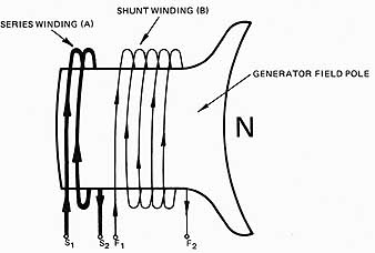
Ill. 2 Compound field windings: GENERATOR FIELD POLE.
When the series winding is connected to aid the shunt winding, the generator is called a cumulative compound-wound generator; if the series winding is connected to oppose the magnetic field, it's called a differential compound-wound generator.
The action of two fields in changing the flux density can be used to improve the volt age regulation of a normal shunt generator. As you recall, as a load is applied in the shunt generator, the output voltage falls because of internal resistance, armature reaction, and the reduction of voltage applied to the field circuit. If the field strength can be automatically increased in proportion to load current as it increases, the output voltage can be maintained at a constant level, increased, or decreased. This is the objective in adding the series winding to the compound generator. As the load current increases in a cumulative-compound connected generator, it passes through the series winding and increases the flux. The additional voltage induced by cutting this flux compensates for the voltage loss due to armature resistance, armature reaction, and lower shunt field voltage.
The number of turns in the series field helps determine the degree of compounding which is achieved. A large number of turns in the series winding produces over-compounding (a voltage increase at full load as compared to the output voltage at no load). A small number of series turns produces a reduced voltage at full load. This effect is called under-compounding.
Flat compound generators have the same voltage output at no load and full load. In industry, this type of generator is used where the distance between the generator and the load is short and line resistance is minimal. Over-compounding generators are used when the transmission distance is long, as in traction service, and the voltage at the end of the line must remain fairly constant.
A comparison of the voltage regulation of a shunt generator and a compound generator for both cumulative and differential connections is illustrated in 3.
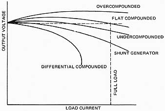
Ill. 3 Compound generator load characteristics.
OUTPUT VOLTAGE CONTROL
The rated voltage of a compound generator operating at rated speed is set by adjusting the field rheostat. Since the compounding effect of the series field changes with speed, it's important to operate a compound generator at its rated speed.
Variation of Compounding
In general, compound-wound generators are designed by the manufacturer to have an over-compounding effect. The amount of compounding can be changed to any desired value by using a diverter rheostat across the series field. In fgr4, a diverter rheostat (R) is connected in shunt (parallel) with the series winding. If the resistance of the diverter is set at a high value, the load current passes through the series winding to produce a maximum compounding effect. If the diverter is set at its minimum value, no load current passes through the series winding and the generator acts like a normal shunt generator. By adjusting the rheostat to intermediate values, any degree of compounding within these limits can be obtained. Flat compounding results when “no load” voltage is equal to “full load” voltage.
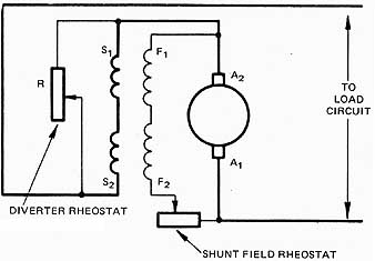
Ill. 4 Diverter circuit: diverter rheostat, shunt
field rheostat
SUMMARY
Compound-wound generators use a series field, connected in series with the load, to react to current load changes. It is connected to aid the shunt field or to oppose the shunt field. In most dc generators the series field will be connected so that the magnetic field produced, aids the shunt field flux. This connection is called a cumulative connection. The degree of compounding can be controlled by a diverter rheostat. If the series field is connected so that the resultant flux opposes the shunt field flux, then the output voltage drops with an increase in current-draw and the generator is differentially connected.
QUIZ
A. Select the correct answer for each of the following statements.
1. A compound-wound generator terminal connection box contains terminal leads
a. F1, F2, and A1, A2
b. S1, S2, and F1, F2
c. S1, S2, and A1, A2
d. S1, S2, F1, F2, and A1, A2
2. The series winding must be large enough to carry:
a. the total magnetic flux.
b. a 300% overload.
c. full line current.
d. full line voltage.
3. Select the type of generator that may be used for loads quite distant from the generator.
a. Over-compounded c. under-compounded
b. flat compounded d. differential compounded
4. The normal voltage of a compound generator is changed by adjusting the ____
a. series field shunt. c. shunt field rheostat.
b. brush setting. d. equalizer.
5. The resistance of a series field diverter should be:
a. comparatively high.
b. equal to the resistance of the series field.
c. a variable resistor.
d. comparatively low.
6. To achieve a maximum compounding effect, the diverter rheostat should be:
a. set at its minimum value.
b. set at a high value.
c. set at a value midway between its minimum and maximum values.
d. removed from the series field circuit.
B. Select the correct answer to questions 7 to 12 from the following list and place it in the space provided.
a. Field poles g. increase
b. diverter rheostat h. flat compounding
c. compound-wound generator i. shunt field rheostat
d. saturate j. over-compounding
e. decrease k. remain constant
f. shunt generator l. under-compounding
7. When it's necessary to provide automatic control of the voltage output at constant speed, the generator selected is a ______
8. The current through the shunt winding of a compound generator isn't sufficient to _____________ the field poles.
9. The terminal voltage output of a cumulative compound-wound generator should ________________ as the load current is increased.
10. When the output voltage of a generator is the same at both no load and full load, the generator is called a ________ type.
11. Compound-wound generators are generally designed to be of the type.
12. The amount of compounding which can be obtained from a generator is controlled by the ________.