AMAZON multi-meters discounts AMAZON oscilloscope discounts
OBJECTIVES:
• state the function of a dc generator.
• list the major components of a generator.
• describe the difference between a separately-excited and a self-excited generator.
• explain how the output voltage of a generator can be varied.

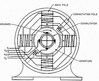
Ill. 1-1: Compound generator fields, with commutating poles:
commutating pole, armature, main pole, brushes, commutator
A dc generator changes mechanical energy into electrical energy. It furnishes electrical energy only when driven at a definite speed by some form of prime mover, such as a diesel engine or a steam turbine.
DC generators are used principally in electrical systems for mobile equipment. They are also used in power plants supplying dc power for factories and in certain railway systems. DC power is used extensively in communication systems and for battery charging and electroplating operations. The generation of electromotive force is described in detail in our ELECTRICITY 1 Guide.
DC GENERATOR COMPONENTS
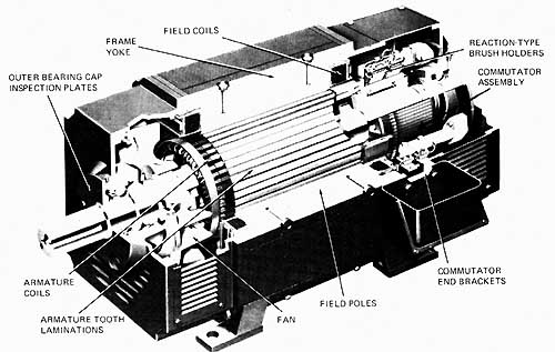
The essential parts of a dc generator are illustrated in 1 and 2. The member that spins is called the rotor. The rotor is a cylindrical, laminated iron core that's mechanically coupled to the drive shaft of the generator. An armature winding is embedded in the slots on the surface of the rotor. The armature windings have voltage induced into them as it spins past the field poles. The windings are actually coils of wire in a series of loops that terminate at the copper segments of the commutator.
A commutator consists of a series of copper segments which are insulated from one another and the shaft. The commutator turns with the shaft and the armature windings. The commutator is used to change the ac voltage induced in the armature windings to dc voltage at the generator output terminals. Carbon brushes pressing against the commutator segments connect the current to the external load circuit.

Ill. 2 Cutaway view of a direct-current generator:
reaction-type brush holders; field coils; frame yoke; outer bearing cap
inspection plates; armature coils; armature tooth laminations; field poles;
commutator end brackets

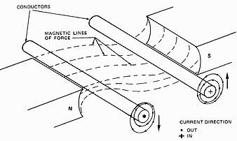
Ill. 3 “Motor action” opposing generator driving force
The armature windings generate voltage by cutting a magnetic field as the armature rotates. This magnetic field is established by electromagnets mounted around the periphery of the generator. The electromagnets, called field poles, are arranged in a definite sequence of magnetic polarity; that's , each pole has a magnetic polarity opposite to that of the field poles adjacent to it. Electrical current for the generator field circuit's usually obtained from the generator itself.
When a generator feeds a load circuit, current passing through the armature sets up a magnetic field around the armature. This field reacts with the main field flux. The result is a force that attempts to turn the armature in a direction opposite to that in which it's being driven (This effect is known as the motor effect of generators). The force of this reaction is proportional to the current in the armature and accounts for the fact that more mechanical power is needed to drive a generator when electrical energy is taken from it.
Armature Reaction
The armature field flux also reacts against the main field flux and tends to distort it. One result of this undesirable condition, known as armature reaction, is excessive sparking at the brushes on the commutator. To counteract this effect, commutating poles are often inserted between the main field poles, as illustrated in 1. These commutating poles, also called inter-poles, are energized by windings placed in series with the output (load) circuit of the generator. Because of this arrangement, armature reaction, which tends to increase with load current, is counteracted by the effects of the load current passing through the interpoles.
Armature reaction, appearing as excessive brush sparking under load, also can be partially corrected by shifting the brushes from their neutral position in the direction of rotation. Large dc generators have the brushes assembled so that they can be shifted to the position of minimum sparking. When the brushes are not movable, the generator manufacturer inserts other design features to minimize the effects of armature reaction.
Brush Polarity
The output terminals of a generator, as with other dc power units, have electrical polarity. In the case of generators, the term brush polarity is used to distinguish between the electrical polarity of the brushes, either positive or negative, and the magnetic polarity either North or South, of the field poles.
Brush polarity markings are often omitted, but the electrician can easily determine electrical polarity by connecting a voltmeter across the output leads of the generator. Many automotive and aircraft generators are constructed with either the positive or negative brushes grounded to the frame of the generator. It is very important to maintain the polarity as specified by the manufacturer. Additional information on brush polarity will be given after the effects of residual magnetism in the field circuit are considered.
Field Supply
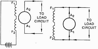
The magnetic field of a generator is established by a set of electromagnets (field poles). The current required by the field circuit may be supplied from a separate dc sup ply. If this is the case, the generator is said to have a separately excited field. The majority of generators, however, are self-excited and the current for the field is supplied by the generator itself.

Ill. 4 Separate excitation; Ill. 5 Self-excitation
ill 4 illustrates a separately excited dc generator with the field circuit supplied from batteries. A self-excited shunt generator is illustrated in 5. Note that the field circuit's connected in parallel with the armature and that a small part of the generator output is diverted to the field circuit, in order to “excite” or energize the field poles.
OUTPUT VOLTAGE CONTROL
Since the induced voltage depends on the rate at which the magnetic lines of force per second are cut, it's possible to vary the output voltage by controlling either the speed of the prime mover or the strength of the magnetic field. In all but a few instances, the output voltage is controlled by varying the field current with a rheostat in the field circuit.
The flux density in the field poles depends on the field current. As a result, the volt age output of the generator continues to increase with an increase of field current to a point where saturation of the field poles occurs. Any additional increase in voltage output after this point must be obtained by an increase in speed.
GENERATOR RATINGS
Generator ratings as specified by the manufacturer are usually found on the name plate of the machine. The manufacturer generally specifies the kilowatt output, current, terminal voltage, and speed of the generator. For large generators, the ambient temperature is also given.
ROTATION
A separately-excited generator develops voltage for either direction of rotation. This isn't true, however, for self-excited units; they develop voltage in one direction only. (See explanation in unit 3.) The standard direction of rotation for dc generators is clock wise when looking at the end of the generator opposite the drive shaft (this is usually the commutator end).
REGULATION
The voltage regulation of a generator is one of its important characteristics. Different types of generators have different voltage regulation characteristics.
ill 6 shows the action of the voltage at the terminals of a generator for different values of the load current. The drop in terminal voltage is caused by the loss in voltage (1) across the internal resistance of the armature circuit including the brush contacts, and (2) due to armature reaction. The curve at (a) is the normal curve for a shunt generator. An ideal condition is shown in (b) where the voltage remains constant with load current. Curve (c) illustrates a generator with very poor regulation in that the output voltage drops off considerably as the load current increases. A rising characteristic, curve (d), is obtained by using a cumulative compound-wound generator (unit 4).
SUMMARY
DC generators are used to provide direct current to specific loads. The armature, mounted on the rotor, is driven through the magnetic fields developed by the electromagnetic poles. AC voltage is actually induced into the armature, then mechanically rectified …
[restore p. 6-8]