AMAZON multi-meters discounts AMAZON oscilloscope discounts
GOALS
• analyze the requirements of a single-family dwelling.
• determine the size of service-entrance conductors.
• select the proper material and demonstrate the proper methods for the service- entrance installation.
The service entrance for most present-day lighting installations is a single-phase, three-wire service.
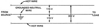
ill. 1 Single-phase, three-wire system.
The middle wire is called the neutral wire and is grounded. Therefore, this neutral wire (grounded conductor) is the identified or white wire of any single-phase, three-wire installation. The two outside wires are known as the hot wires (conductors). The voltage between the neutral wire and either of the two hot wires is 115 volts, and the voltage between the two hot wires is 230 volts.
It is an advantage to have both 115 and 230 volts available. Many types of loads, such as electric water heaters, electric ranges and fractional horsepower motors, operate on 230 volts.
Service-entrance voltages have gradually increased in many parts of the country. Therefore, it's not uncommon to find 120 volts and 240 volts as standard voltages.
TYPICAL SINGLE-FAMILY DWELLING
It is the intent of this unit to present the fundamental installation rules for a service entrance insofar as they concern the calculations that affect the service-entrance switch, service-entrance conductors, and grounding. The branch circuits supplying the various items of electrical equipment in a residence are covered briefly. The metering facilities for electrical space-heating equipment as well as electric water heaters vary according to the requirements of the local utility company. As a result, it's not possible to cover all of these metering methods in detail. The electrician must check the requirements for these installations with the utility company serving the area in which the wiring is to be installed.
A typical application for a 115/230-volt, single-phase, three-wire service installation is a single-family dwelling. The residence considered in this unit's a six-room house (including three bedrooms) with an area of 1,500 square feet (1,500 ft^2) The residence contains a 3-kW water heater; a 5.0-kW clothes dryer; an 8-A, 230-V room air conditioner; a dishwasher rated at 11.1A, 115 V; a 4-kW wallmounted oven; a 6-kW countermounted cooking unit; a garbage disposal rated at 7.5 A, 115 V; and 12 kW of electric space-heating equipment installed for all six rooms. Each room has individual thermostatic control.
Determination of Number of Lighting Circuits
To determine the number of lighting circuits, the lighting load of the residence must be calculated. The calculations are based on the watts per square foot method outlined in the National Electrical Code (referred to here as “the Code”). In general, the outside dimensions of the building are used, not including open porches, garages, unfinished attics, or basements. For the residence in question, the area is 1,500 square feet. The recommended unit load is 3 watts per square foot.
Therefore, the total lighting load in watts is:
1,500 square feet x 3 watts per square foot = 4,500 watts
To determine the minimum number of 115-volt branch lighting circuits:
amperes = watts/volts = 4,500/115 = 39.1 or 40 amperes
In general, 15-ampere lighting circuits using No. 14 AWG conductors are installed in residential occupancies. Some electrical specifications require a minimum conductor size of No. 12 AWG on all circuits.
Thus 40/15 = 2 plus or 3 lighting circuits (minimum)
However, a residence of this type may have as many as 60 outlets, including ceiling fixtures, porch fixtures, and wall convenience receptacles located throughout the living area, basement, garage, and grounds. As a result, most electricians prefer to limit the number of outlets per circuit to 8 or 10. This results in a more adequate number of lighting circuits. For the residence covered in this unit, at least 6 lighting circuits will be installed even though the minimum number of circuits required is 3.
Determination of Number of Small Appliance Circuits
The Code specifies that for small appliances an additional load of not less than 1,500 watts shall be included for each circuit for the receptacle outlets. These circuits shall feed only receptacle outlets in the kitchen, pantry, family room, dining room, and breakfast room of a dwelling. Two or more 20-ampere branch circuits shall be provided, and such circuits shall have no other outlets. No. 12 AWG wire is used instead of No. 14 AWG wire to minimize the voltage drop in the circuit. Thus, by using the larger wire, the performance of appliances is improved and the danger of overloading circuits is decreased.
Since automatic washing machines draw a large amount of current during certain portions of their operating cycles, the Code requires that a separate 20-ampere circuit for the laundry outlets be installed. All convenience receptacles must be of the grounding type.
To determine the service-entrance requirements of this dwelling, the small appliance load is assumed to be 4,500 watts, based on three 20-ampere circuits at 1,500 watts per circuit.
Garbage Disposal. The garbage disposal unit's rated at 7.5 amperes, 115 volts, and will be supplied by a separate 15-ampere circuit which requires No. 14 AWG conductors.
The garbage disposal load is:
7.5 amperes x 115 volts = 862 watts
Dishwasher. The dishwasher is rated at 11.1 amperes, 115 volts, and will be supplied by a separate 15-ampere circuit using No. 14 AWG wire. (It is possible to supply the garbage disposal unit and the dishwasher with one 115/230-volt, three-wire circuit.)
The dishwasher load in watts is:
11.1 amperes x 115 volts = 1,276 watts
Dryer Circuit. The electric clothes dryer is rated at 5.0 kW, 230 V. The current it draws is:
5,000 watts/230 volts = 21.7 amperes
The Code states that the branch-circuit rating for continuous duty loads shall be not less than 125 percent of the rating of the appliance.
21.7 amperes x 1.25 = 27.1 amperes
The circuit to the dryer will be a 30-ampere, 230-volt, three-wire circuit consisting of two No. 10 AWG conductors for the hot wires and one No. 10 AWG conductor for the neutral conductor.
Wallmounted Oven. The oven is rated at 4 kW, 115/230 V and will be connected to a separate circuit. In watts, the load is 4,000 watts; in amperes, the load is equal to:
amperes = watts/ volts=4000/230=17.4 amperes
No. 12 AWG wire may be used for this circuit.
Countermounted Cooking Unit. The surface cooking unit's rated at 6 kW, 115/230 V. The unit will be connected to a separate circuit consisting of three No. 10 AWG conductors supplied by a 30-ampere, two-pole overcurrent device.
The load, in amperes, is:
amperes = watts/volts = 600/230 = 26A
Air Conditioner. The room air conditioner draws 8 amperes at 230 volts and will be connected to a separate 15-ampere, 230-volt circuit with No. 14 AWG conductors (15 amperes).
The air conditioner load, in watts, is:
8 amperes x 230 volts = 1,840 watts
Water Heater. Many utility companies furnish current for residential electric water heater loads at a power consumption rate lower than the regular lighting rate. In such installations, some utility companies require a separate off-peak meter, while other companies predetermine a fixed portion of the monthly light bill to cover the power consumption of the water heater.
In general, for the off-peak metering circuit, the top element of the heater is connected to a two-pole, 230-volt circuit supplied through the house meter. The bottom element of the heater is connected to a two-pole, 230-volt circuit supplied through the off-peak meter. These elements can be connected for limited demand, in which case both elements cannot be energized simultaneously; or they may be connected for unlimited demand, in which case both elements may be energized simultaneously. The types of thermostats furnished with the water heater determine how the elements are connected.
Various types of equipment are manufactured in which both regular and off-peak overcurrent protective devices may be located in the same enclosure. The off-peak device is called a feed-through unit and isn't connected in any manner to the main bus of the panel even though it's located in the same enclosure. In the feed-through unit, the two wires from the off-peak meter are connected to one side of the unit, and the two wires sup plying the element of the water heater are connected to the other side.
The water heater in this residence is rated at 3 kW. This load, in amperes, is equal to:
amperes =watts / volts = 3,000 / 230 =13 amperes
When connected for unlimited demand, the maximum current of this water heater is 13 amperes.
Consult the local utility company for guidelines on the proper connection of water heaters.
Electric Space Heating. The specified total of 12 kW of electric space heating units will be installed throughout the residence. Each of the six rooms will have a thermostat to provide individual heating control. According to the National Electrical Code, there must be four or more individually controlled electric space heating units to apply certain demand factors permitted by the Code. These factors are used to calculate the ser vice-entrance capacity. Approximately 2 kW of space heat will be provided in each room. Since these units are rated at 230 volts, the load for each is:
amperes = watts/volts = 2,000 / 230 = 8.7A
The branch-circuit current rating is 125 percent of the load, or, 1.25 x 8.7 = 10.9 amperes.
Therefore, each unit will be connected to a separate 15-ampere, 230-volt circuit using No.14 AWG wire.
Some utility companies offer lower rates for electric heating when this is a residential requirement in addition to general electrical services. These rates usually are based on special metering methods. The electrician should consult the utility company supplying power in a local area for the correct method of connecting heating loads.
Summary of Branch Circuits for the Residence:
No. of Circuits |
Voltage |
Use |
Branch-Circuit Ampere Rating |
Poles |
Wire Size (AWG No.) |
6 3 1 1 1 1 1 1 1 6 |
115 115 115 115 115/230 115/230 115/230 230 230 230 |
General lighting Small appliance and laundry Garbage disposal Dishwasher Dryer Oven Surface cooking unit Air conditioner Water heater Space heat |
15 20 15 15 30 20 30 15 20 15 |
1 1 1 1 2 2 2 2 2 2 |
14 12 14 14 10 12 10 14 12 14 |
SIZE OF SERVICE-ENTRANCE CONDUCTORS
Section 230-42 of the National Electrical Code specifies that service-entrance conductors shall have a current-carrying capacity sufficient to carry the load as determined by Article 220 For dwelling occupancies, the Code permits the use of either of two methods to determine the size of these conductors
Method Number 1 (Standard Method) (Article 220, Parts A and B)
General Lighting Load
15,00 square feet at 3 watts per square foot: 4,500 watts
Small Appliance Load (Section 220-16):
Three 20-ampere appliance circuits at 1,500 watts per circuit: 4,500 watts
Total (without range): 9,000 watts
Application of demand factor (Table 220-11):
3,000 watts at 100% = 3,000 watts
9,000 - 3,000 = 6,000 watts at 35% = 2,100 watts
Net computed load without range 5,100 watts
Wallmounted Oven and Countermounted Cooking Unit (Table 220-19, Note 4):
6,000 + 4,000 = 10,000 watts at 80% = 8,000 watts
Net computed load with range (5,100 + 8,000) = 13,100 watts
Electric Space Heating (Section 220-15) 12,000 watts
Air conditioning wattage is 8 x 230 = 1,840 watts. This value is less than the 12,000 watts of space heating; therefore, the air conditioner load need not be included in the service calculation (Section 220-21).
Water Heater .... 3,000 watts
Dryer 5,000 watts
Dishwasher .... 1,276 watts
Garbage Disposal (862 x 1.25)
[Section 210-22(a)] 1,077 watts
Total .... 10,353 watts
Since there are four appliances in addition to the cooking units and space heating, a demand factor of 75 percent may be applied to the fixed appliance load (Section 220-17).
Thus, 10,353 x 0.75 = 7,765 watts
Total Calculated Load: 13,100 + 12,000 + 7,765 = 32,865 watts
Amperes = watts/volts = 32,865/230 = 142.9 amperes
According to Table 310-16 Note 3 of the Code, for a load of 142.9 amperes, No. 1 RHW or THW wire may be installed as the copper service-entrance conductors.
It should be noted that for single-family residences with initial load of 10 kW or more, computed in accordance with Article 220, there shall be a minimum of a 100- ampere, three-wire service. This minimum also applies to residences that have six or more two-wire branch circuits [23042(b)].
Method Number 2 (Article 220, Part C)
An optional method of determining the load of a single-family dwelling is recognized by the Code in Section 220-30. This method simplifies the calculations and usually results in a smaller size of service entrance than is permitted by Method 1.
1,500 square feet at 3 watts per square foot .... 4,500 watts
Three 20-ampere appliance circuits at 1,500 watts per circuit .... 4,500 watts
Wallmounted oven (nameplate rating) .... 4,000 watts
Countermounted cooking unit (nameplate rating) .... 6,000 watts
Water heater .... 3,000 watts
Dryer .... 5,000 watts
Dishwasher .... 1,276 watts
Garbage disposal (862 x 1.25) [ 210-22(a)] .... 1,077 watts
Electric space heating 12,000 watts
Air conditioner wattage is 8 x 230 = 1,840 watts. This value is less than the 12,000 watts of space heating; therefore, the air conditioner load need not be included in the service calculation. [220-21] _____
Total load.... 41,353 watts
Then: first 10 kWh at 100% =10,000 watts
remainder of load at 40% (31,353 x 0.4) = 12,541 watts
Total Calculated Load.... 22,541 watts
Amperes = watts/volts = 22,541/230 = 98 amperes
According to Table 310-16 of the Code, for a load of 98 amperes, No. 4 RHW wire or equivalent may be installed as the copper service-entrance conductors.
Both Methods 1 and 2 for determining total load are correct as far as the Code is concerned. Therefore, the decision as to which method is permitted in an area is made by the local electrical inspector.
To provide a single panel which will accommodate all the circuits in the residence, it's necessary to install a 200-ampere panel.
Certain localities require that the conductors supplying a panel or switch must have a current-carrying capacity equal to the rating of the panel or switch. Therefore, for the residence covered in this unit, No. 2/0 RHW or equivalent wire is required for the service entrance. The installation of No. 2/0 RHW wire or equivalent will give the homeowner full 200-ampere capacity. See Note 3 to Table 310-1 6.
Service-Entrance Switch (Sections 230-70 and 230-71)
Section 230-71 of the National Electrical Code in essence specifies that the service disconnecting means shall consist of not more than six switches or six circuit breakers in a single enclosure, in a group of separate enclosures, or in or on a switchboard. It is the intent of this section to insure that all electrical equipment within a building can be disconnected with no more than six manual operations. However, certain local ordinances don't permit the six subdivision rule but rather require that each service shall have a single main disconnect.
To accommodate the number of circuits listed in the Summary of Branch Circuits for the Residence, a 200-ampere panel will be installed. This panel will contain all of the required branch circuits plus a 200-ampere main pullout in one enclosure. This type of enclosure is acceptable as both the load center and service equipment, and meets Code requirements in most localities.
Generally, the service switch is located in the basement and the meter is mounted on the outside of the house for easy access by the utility company.
Ground Connection
Section 250-5(b) (1) of the Code requires the grounding of interior alternating current systems where the system can be grounded so that the maximum voltage to ground, on the ungrounded conductors, does not exceed 150 volts. Grounding is accomplished by running a wire from the neutral connection in the main service switch or meter to the water piping system on the street side of the water meter. The reason for connecting on the street side of the water meter is so that the ground circuit remains connected if the meter must be removed for repair.
Sections 250-91 and 250-92 set forth the rules governing grounding materials and the installation of the ground wire. The size of ground wire required is found in Table
250-94. It was mentioned previously that the residence covered in this unit will be sup plied with No. 2/0 RHW service-entrance conductors. According to Table 250-94, No. 2/0 RHW conductors require a No. 4 AWG grounding conductor.
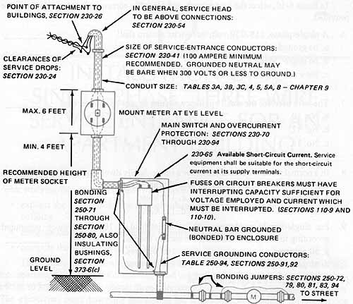
Note: It is beyond the scope of this unit to illustrate all the methods of metering the water heater and electrical space heating load. ill 11-2, therefore, illustrates the entire load connected to a single meter. This figure is used only to outline the installation requirements.
Bonding
The proper bonding of all service-entrance equipment is as important as the use of the proper size of service conductors. Section 250-71 lists the equipment that shall be bonded and Section 250-72 lists the methods approved for bonding this equipment. Bonding jumpers shall have a current-carrying capacity not less than is required for the corresponding grounding conductor.
The purpose of bonding on service-entrance equipment is to assure a low impedance path to ground should a fault occur on any of the service-entrance conductors. Severe arcing, which presents a fire hazard, may occur at a fault. Proper bonding reduces this hazard to some extent.
The fire hazard exists because the service-entrance conductors are not fused at the service head. The short-circuit current on these conductors is limited only by the capacity of the transformer or transformers supplying the service equipment and the distance the service equipment is located from these transformers. Short-circuit current can easily reach 10,000 amperes in residential areas and as high as 200,000 amperes in industrial areas. All overcurrent devices (fuses and circuit breakers) must have adequate interrupting capacity. See Sections 110-9 and 230-98 of the Code.
QUIZ
1. State one reason why the single-phase, 115/230-volt, three-wire system is used in present-day installations instead of a 115-volt, two-wire system.
|
|
2. State how the area, in square feet, for a single-family dwelling is determined to arrive at the approximate lighting load.
3. What is the number of watts per square foot allowed by the Code when determining the lighting load for a single-family dwelling?
4. What is the minimum number of appliance circuits permitted by the Code for a single-family dwelling?
5. Explain why the ground wire is connected to the street side of the water meter in installations where there is a public water system.
In items 6-10, select the best answer, and place the corresponding letter in the space provided.
6. A single-phase, 115 /230-volt, three-wire system shall
a. be grounded.
b. be ungrounded.
c. have one appliance circuit.
d. have No. 12 service-entrance wires.
7. The wire used for the small appliance circuits cannot be smaller than
a. No. 10.
b. No. 12.
c. No. 14.
d. No. 16.
8. In a normal three-wire installation for a single-family dwelling, the voltage from one ungrounded wire to the grounded neutral is approximately
a. 460 volts. c. 150 volts.
b. 230 volts. d. 115 volts.
9. For single-family residences with an initial load of 10 kW or more, computed according to acceptable methods, the service shall be at least ______
a. 50 amperes. c. 100 amperes.
b. 80 amperes. d. 120 amperes.
10. Service-entrance equipment shall be
a. of a common size for all installations.
b. bonded.
c. stapled.
d. selected before the load is determined.
11. Determine the minimum number of 115-volt lighting circuits necessary in a single-family dwelling with an active area of 2,300 square feet.
12. A single-family dwelling has a 7.6-kW, 115/230-volt electric range. Determine the minimum size of the conductors to be used for the range feeder from the service entrance cabinet to the range outlet.