AMAZON multi-meters discounts AMAZON oscilloscope discounts
LEARNING OBJECTIVES:
- • discuss the operation of a d'Arsonval meter movement.
- • connect a voltmeter to a circuit.
- • connect and read an analog multimeter.
- • connect an ammeter.
- • measure resistance using an ohmmeter.
GLOSSARY OF MEASURING INSTRUMENT TERMS:
- ammeter --a device for measuring current flow
- ammeter shunt --a device that allows an ammeter to measure large amounts of current; the shunt is connected in series with the load and the ammeter is connected in parallel with the shunt
- analog meters -- meters that employ a moving pointer to indicate a value
- clamp-on ammeter --an ammeter with a movable jaw that can be clamped around a conductor to measure current flow current transformer a transformer used to measure large values of AC current
- d'Arsonval movement -- a galvanometer that employs a moving coil suspended inside a permanent magnet to move a pointer
- galvanometers --very sensitive meters that require only a few microamperes of current to operate
- multirange voltmeters --volt meters that employ more than one full range value
- ohmmeter --a meter used to measure values of resistance
- voltmeter --a meter used to measure voltage
Anyone desiring to work in the electrical and electronics field must become proficient with the common instruments used to measure electrical quantities. These instruments are the voltmeter, ammeter, and ohmmeter. Without meters it would be impossible to make meaningful interpretations of what is happening in a circuit. Meters can be divided into two general types: analog and digital.
ANALOG METERS
Analog meters are characterized by the fact that they use a pointer and scale to indicate their value ( FIG. 1). There are different types of analog meter movements. One of the most common is the d'Arsonval movement shown in FIG. 2. This type of movement is often referred to as a moving coil meter. A coil of wire is suspended between the poles of a permanent magnet, either by jeweled movements similar to those used in watches or by taut bands. The taut band type offers less turning friction than the jeweled movement. These meters can be made to operate on very small amounts of current and often are referred to as galvanometers.
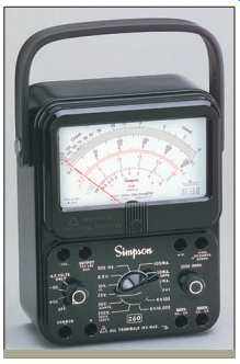
FIG. 1 An analog meter. Simpson Electric.
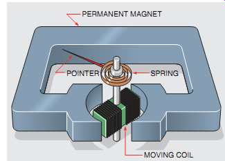
FIG. 2 Basic d'Arsonval meter movement. PERMANENT MAGNET POINTER SPRING;
MOVING COIL; PRINCIPLE OF OPERATION
Analog meters operate on the principle that like magnetic poles repel each other. As current passes through the coil, a magnetic field is created around the coil. The direction of current flow through the meter is such that the same polarity of magnetic pole is created around the coil as that of the permanent magnet. This like polarity causes the coil to be deflected away from the pole of the magnet. A spring is used to retard the turning of the coil. The distance the coil turns against the spring is proportional to the strength of the magnetic field developed in the coil. If a pointer is added to the coil and a scale is placed behind the pointer, a meter movement is created.
Since the turning force of this meter depends on the repulsion of magnetic fields, it will operate on DC current only. If an AC current is connected to the moving coil, the magnetic polarity will change 60 times per second and the net turning force will be zero. For this reason, a DC voltmeter will indicate zero if connected to an AC line. When this type of movement is to be used to measure AC values, the current must be rectified, or changed into DC, before it’s applied to the meter ( FIG. 3).
THE VOLTMETER
The voltmeter is designed to be connected directly across the source of power. FIG. 4 shows a volt meter being used to test the voltage of a battery.
Notice that the leads of the meter are connected directly across the source of voltage. A voltmeter can be connected directly across the power source because it has a very high resistance connected in series with the meter movement ( FIG. 5). The industrial standard for a voltmeter is 20,000 ohm per volt for DC and 5000 ohm per volt for AC.
Assume the voltmeter shown in FIG. 5 is an AC meter and has a full scale range of 300 V.
The meter circuit (meter plus resistor) would have a resistance of 1,500,000 ohm (300 Vx5000 ohm per volt=1,500,000 ohm).
RECTIFIER AC VOLTS
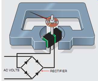
FIG. 3 Rectifier changes AC voltage into DC voltage.
FIG. 4 A voltmeter connects directly across the power source.
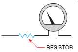
FIG. 5 A resistor connects in series with the meter.
CALCULATING THE RESISTOR VALUE
Before the resistor value can be computed, the operating characteristics of the meter must be known. It will be assumed that the meter requires a current of 50 µA and a voltage of 1 V to deflect the pointer full scale. These are known as the full scale values of the meter.
When the meter and resistor are connected to a source of voltage, their combined voltage drop must be 300 V. Since the meter has a voltage drop of 1 V, the resistor must have a drop of 299 V. The resistor and meter are connected in series with each other.
In a series circuit, the current flow must be the same in all parts of the circuit. If 50 µA of current flow is required to deflect the meter full scale, then the resistor must have a current of 50 µA flowing through it when it has a voltage drop of 299 V. The value of resistance can now be computed
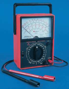
FIG. 6 Volt-ohm-milliammeter with multi-range selection. Triplett Corp.
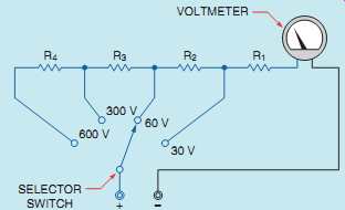
FIG. 7 A rotary selector switch is used to change the full range setting.
MULTIRANGE VOLTMETERS
Most voltmeters are multirange voltmeters, which means that they are designed to use one meter movement to measure several ranges of voltage.
For example, one meter may have a selector switch that permits full scale ranges to be selected.
These ranges may be 3 V full scale, 12 V full scale, 30 V full scale, 60 V full scale, 120 V full scale, 300 V full scale, and 600 V full scale. Meters are made with that many scales so that they will be as versatile as possible. If it’s necessary to check for a voltage of 480 V, the meter can be set on the 600-V range. It would be very difficult, however, to check a 24-V system on the 600-V range. If the meter is set on the 30-V range, it’s simple to test for a voltage of 24 V.
The meter shown in FIG. 6 has multirange selection for voltage.
When the selector switch of this meter is turned, steps of resistance are inserted in the circuit to increase the range or removed from the circuit to decrease the range. The meter shown in FIG. 7 has four range settings for full scale voltage: 30 V, 60 V, 300 V, and 600 V. Notice that when the higher voltage settings are selected, more resistance is inserted in the circuit.
CALCULATING THE RESISTOR VALUES
The values of the four resistors shown in FIG. 7 can be determined using Ohm's law. Assume that the full scale values of the meter are 50 µA and 1 V.
The first step is to determine the value for resistor R1, which provides a full scale value of 30 V. Resistor R1, therefore, must have a voltage drop of 29 V when a current of 50 µA is flowing through it.
R = E/I
R = 29/0:000050
R = 580 k ohm=580,000 ohm
When the selector switch is moved to the second position, the meter circuit should have a total voltage drop of 60 V. The meter movement and resistor R1 have a total voltage drop of 30 V, so resistor R2 must have a voltage drop of 30 V when 50 µA of current flow through it. This will provide a total voltage drop of 60 V for the entire circuit.
R = E/I
R = 30/50 µ (000050A )
R = 600 k ohm=600,000 ohm
When the selector switch is moved to the third position, the circuit must have a total voltage drop of 300 V. Resistors R1 and R2 plus the meter movement have a combined voltage drop of 60 V at rated current. Resistor R3, therefore, must have a voltage drop of 240 V at 50 µA.
R = E/I
R = 240/50 µA
R = 4:8M ohm=4,800,000 ohm
When the selector switch is moved to the fourth position, the circuit must have a total voltage drop of 600 V at rated current. Since resistors R1,R2, and R3 plus the meter movement produce a voltage drop of 300 V at rated current, resistor R4 must have a voltage drop of 300 V when 50 µA of cur rent flow through it.
R = E/I
R = 300/50 µA
R = 6M ohm=6,000,000 ohm
READING A METER
Learning to read the scale of a multimeter takes time and practice. Most people use meters every day with out thinking about it. A common type of meter used daily by most people is shown in FIG. 8.Itisa speedometer similar to those seen in automobiles.
This meter is designed to measure speed. It’s calibrated in miles per hour. The speedometer shown has a full scale value of 80 mph. If the pointer is positioned as shown in FIG. 8, most people would know instantly that the speed of the auto mobile is 55 mph.
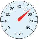
FIG. 8 A speedometer.
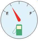
FIG. 9 A fuel gauge.
FIG. 9 illustrates another common meter used by most people. This meter measures the amount of fuel in the tank of the automobile.
Most people can glance at the pointer and know that the meter is indicating that there is one quarter of a tank of fuel remaining. Now assume that the tank has a capacity of 20 gallons. The meter is indicating that 5 gallons of fuel remain in the tank.
Learning to read the scale of a multimeter is similar to learning to read a speedometer or fuel gauge. The meter scale shown in FIG. 10 has several scales used to measure different quantities and values. The top of the scale measures resistance, or ohms. Notice that the scale begins on the left at infinity and ends at zero on the right.
Ohmmeters will be covered later in this section.
The second scale is labeled AC-DC and is used to measure voltage. Notice that this scale has three different full scale values. The top scale is 0-300, the second scale is 0-60, and the third scale is 0-12. The scale used is determined by the setting of the range control switch. The third set of scales is labeled AC amps. This scale is used with a clamp-on ammeter attachment that can be used with some meters. The last scale is labeled dBm, which is used to measure decibels.
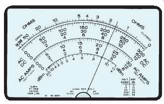
FIG. 10 A typical multimeter.
READING A VOLTMETER
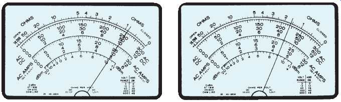
(left) FIG. 11 Reading the meter. (right) FIG. 12 Reading the meter.
Notice that the three voltmeter scales use the primary numbers 3, 6, and 12, and are in multiples of 10 of these numbers. Since the numbers are in multiples of 10, it’s easy to multiply or divide the readings in your head by moving a decimal point.
Remember that any number can be multiplied by 10 by moving the decimal point one place to the right, and any number can be divided by 10 by moving the decimal point one place to the left.
For example, if the selector switch were set to permit the meter to indicate a voltage of 3 V full scale, the 300-V scale would be used, and the reading would be divided by 100. The reading can be divided by 100 by moving the decimal point two places to the left. In FIG. 11, the pointer is indicating a value of 250. If the selector switch is set for 3 V full scale, moving the decimal point two places to the left will give a reading of 2.5 V. If the selector switch were set for a full scale value of 30 V, the meter shown in FIG. 11 would be indicating a value of 25 V. That reading is obtained by dividing the scale by 10 and moving the decimal point one place to the left.
Now assume that the meter has been set to have a full scale value of 600 V. The pointer in FIG. 12 is indicating a value of 44. Since the full scale value of the meter is set for 600 V, use the 60-V range and multiply the reading on the meter by 10. By moving the decimal point one place to the right, the correct reading becomes 440 V.
Three distinct steps should be followed when reading a meter. These steps are especially helpful for someone who has not had a great deal of experience reading a multimeter. The steps are:
1. Determine what the meter indicates. Is the meter set to read a value of DC voltage, DC current, AC voltage, AC current, or ohms? It’s impossible to read a meter if you don't know what the meter is used to measure.
2. Determine the full scale value of the meter. The advantage of a multimeter is that it can measure a wide range of values and quantities. After determining what quantity the meter is set to measure, it must be determined what the range of the meter is. There is a great deal of difference in reading when the meter is set to indicate a value of 600 V full scale and when it’s set for 30 V full scale.
3. Read the meter. The last step is to determine what the meter is indicating. It may be necessary to determine the value of the hash marks on the meter face for the range for which the selector switch is set. If the meter in FIG. 10 is set for 300 V full scale, each hash mark has a value of 5 V.
If the full scale value of the meter is 60 volts, how ever, each hash mark has a value of 1 V.
THE AMMETER
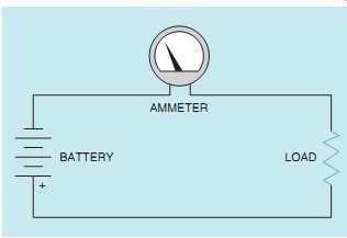
FIG. 13 An ammeter connects in series with the load.
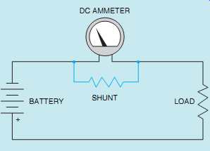
FIG. 15 A shunt is used to set the value of the ammeter.
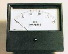
FIG. 14 In-line ammeter.
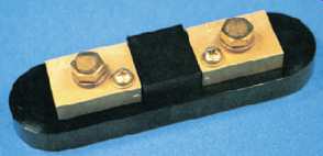
FIG. 16 Ammeter shunt.
The ammeter, unlike the voltmeter, is a very low impedance device. The ammeter is used to measure current and must be connected in series with the load to permit the load to limit the current flow ( FIG. 13). An ammeter has a typical impedance of less than 0.1 Ohm. If this meter is connected in parallel with the power supply, the impedance of the ammeter is the only thing to limit the amount of current flow in the circuit. Assume that an ammeter with a resistance of 0.1 ohm is connected across a 240-V AC line. The current flow in this circuit would be 2400 A (240/0.1=2400). A blinding flash of light would be followed by the destruction of the ammeter.
Ammeters connected directly into the circuit as shown in FIG. 13 are referred to as in-line ammeters. FIG. 14 shows an ammeter of this type.
AMMETER SHUNTS
DC ammeters are constructed by connecting a common moving coil type of meter across a shunt. An ammeter shunt is a low-resistance device used to conduct most of the circuit current away from the meter movement. Since the meter movement is connected in parallel with the shunt, the voltage drop across the shunt is the voltage applied to the meter. Most ammeter shunts are manufactured to have a voltage drop of 50 mV (millivolts).
If a 50-mV meter movement is connected across the shunt as shown in FIG. 15, the pointer will move to the full scale value when the rated current of the shunt is flowing. In the example shown, the ammeter shunt is rated to have a 50-mV drop when a 10-A current is flowing in the circuit.
Since the meter movement has a full scale voltage of 50 mV, it will indicate the full scale value when 10 A of current are flowing through the shunt. An ammeter shunt is shown in FIG. 16.
Ammeter shunts can be purchased to indicate different values. If the same 50-mV movement is connected across a shunt designed to drop 50 mV when 100 A of current flow through it, the meter will now have a full scale value of 100 A.
The resistance of an ammeter shunt can be computed using Ohm's law. The resistance of a shunt designed to have a voltage drop of 50 mV when 100 A of current flow through it is:
R = E/I
R = 0:050 100 R = 0:0005 Ohm, or 0:5 mO
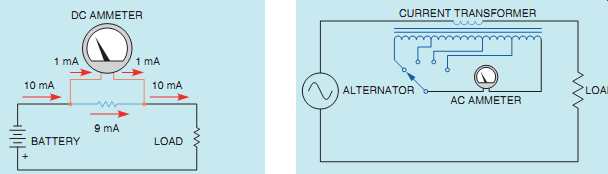
FIG. 17 The total current is divided between the meter and the shunt. FIG. 18
A current transformer is used to change the range of an AC ammeter.
In this problem, no consideration is given to the electrical values of the meter movement. The reason is that the amount of current needed to operate the meter movement is so small compared with the 100-A circuit current that it could have no meaningful effect on the resistance value of the shunt. When computing the value for a low current shunt, however, the meter values must be taken into consideration. For example, assume the meter has a voltage drop of 50 mV (0.050 V) and requires a current of 1 mA (0.001 A) to deflect the meter full scale. Using Ohm's law, it can be found that the meter has an internal resistance of 50 ohm (0.050/0.001=50). Now assume that a shunt is to be constructed that will permit the meter to have a full scale value of 10 mA. If a total of 10 mA is to flow through the circuit and 1 mA must flow through the meter, then 9 mA must flow through the shunt ( FIG. 17). Since the shunt must have a voltage drop of 50 mV when 9 mA of current are flowing through it, its resistance must be 5.555 ohm (0.050/0.009=5.555).
AC AMMETERS
Shunts can be used with AC ammeters to increase their range, but cannot be used to decrease their range. Most AC ammeters use a current transformer instead of shunts to change scale values. This type of ammeter is shown in FIG. 18. The primary of the transformer is connected in series with the load, and the ammeter is connected to the secondary of the transformer. Notice that the range of the meter is changed by selecting different taps on the secondary of the current transformer. The different taps on the transformer provide different turns ratios between the primary and secondary of the transformer. The turns ratio is the ratio of the number of turns of wire in the primary as compared with the number of turns of wire in the secondary.
COMPUTING THE TURNS RATIO
In this example, it will be assumed that an AC meter movement requires a current flow of 100 mA to deflect the meter full scale. It’s also assumed that the primary of the current transformer contains 5 turns of wire. A transformer will be designed to provide full scale current readings of 1 A, 5 A, and 10 A. To find the number of turns required in the secondary winding, the following formula can be used.
Np Ns = Is Ip
...where Np = number of turns of wire in the primary Ns = number of turns of wire in the secondary Ip = current of the primary Is = current of the secondary The number of turns of wire in the secondary to produce a full scale current reading of 1 A can be computed as follows:
5 Ns = 0:1 1
Cross-multiplication is used to solve the problem. Cross-multiplication is accomplished by multiplying the bottom half of the equation on one side of the equals sign by the top half of the equation on the other side of the equals sign.
0:1Ns = 5 Ns = 50
The transformer secondary must contain 50 turns of wire if the ammeter is to indicate a full scale reading when 1 A of current flows through the primary winding.
The number of secondary turns can be found for the other values of primary current in the same way.
5 Ns = 0:1 5
0:1Ns = 25 Ns = 250 turns 5 Ns = 0:1 10
0:1Ns = 50 Ns = 500 turns
CURRENT TRANSFORMERS (CTs)
When a large amount of AC current must be measured, a different type of current transformer is connected in the power line. These transformers have ratios that start at 200:5 and can have ratios of several thousand to five. These current transformers, generally referred to in industry as CTs, have a standard secondary current rating of 5 A AC.
They are designed to be operated with a 5-A AC ammeter connected directly to their secondary winding, which produces a short circuit. CTs are designed to operate with the secondary winding shorted. The secondary winding of a CT should never be opened when there is power applied to the primary. This will cause the transformer to produce a step-up in voltage that could be high enough to kill anyone who comes in contact with it.
A current transformer is basically a toroid transformer. A toroid transformer is constructed with a hollow core similar to a doughnut ( FIG. 19).
When current transformers are used, the main power line is inserted through the opening in the transformer ( FIG. 20). The power line acts as the primary of the transformer and is considered to be 1 turn.
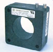
FIG. 19 A toroid current transformer. SQUARE D COMPANY.
ALTERNATOR 5 A AC LOAD CURRENT TRANSFORMER POWER LINE ACTS AS A PRIMARY WINDING OF 1 TURN.
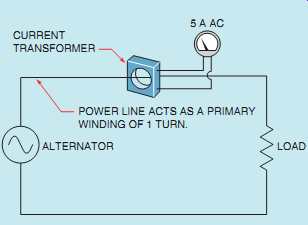
FIG. 20 Toroid transformer used to change the scale factor of an AC ammeter.
The turns ratio of the transformer can be changed by looping the power wire through the opening in the transformer to produce a primary winding of more than 1 turn. For example, assume a current transformer has a ratio of 600:5. If the primary power wire is inserted through the opening, it will require a current of 600 A to deflect the meter full scale. If the primary power conductor is looped around and inserted through the window a second time, the primary now contains 2 turns of wire instead of 1 ( FIG. 21). It now requires 300 A of current flow in the primary to deflect the meter full scale. If the primary conductor is looped through the opening a third time, it would require only 200 A of current flow to deflect the meter full scale.
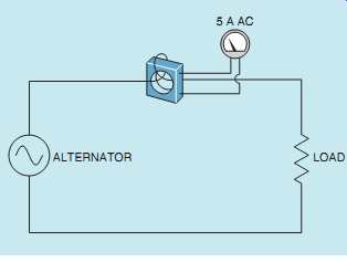
FIG. 21 The primary conductor loops through the CT to produce a second
turn, which changes the ratio.
CLAMP-ON AMMETERS
Many electricians use the clamp-on type of AC ammeter (FIG. 22). The jaw of the meter is clamped around one of the conductors supplying power to the load ( FIG. 23). The meter is clamped around only one of the lines. If it’s clamped around more than one line, the magnetic fields of the wires cancel each other and the meter indicates zero.
The clamp-on meter also uses a current transformer to operate. The jaw of the meter is part of the core material of the transformer. When the meter is connected around the current-carrying wire, the changing magnetic field produced by the AC current induces a voltage into the current trans former. The strength and frequency of the magnetic field determine the amount of voltage induced in the current transformer. Because 60 Hz is a standard frequency throughout the country, the amount of induced voltage is proportional to the strength of the magnetic field.
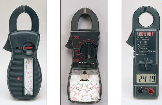
FIG. 22 (A) Analog type clamp-on ammeter with vertical scale. (B) Analog
type clamp-on ammeter with flat scale. (C) Clamp-on ammeter with digital
scale. Amprobe Instrument.
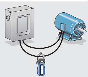
FIG. 23 The clamp-on ammeter connects around only one conductor.
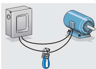
FIG. 24 Looping the conductor around the jaw of the ammeter changes the
ratio.
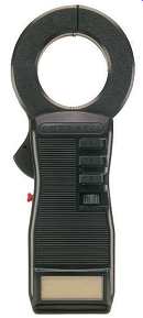
FIG. 25 DC-AC clamp-on ammeter. Amprobe Instrument.
The clamp-on ammeter can be given different range settings by changing the turns ratio of the secondary of the transformer just as is done on the in line ammeter. The primary of the transformer is the conductor around which the movable jaw is connected. If the ammeter is connected around one wire, the primary has one turn of wire compared with the turns of the secondary. The turns ratio can be changed in the same manner that the ratio of the CT is changed. If 2 turns of wire are wrapped around the jaw of the ammeter ( FIG. 24), the primary winding now contains 2 turns instead of 1, and the turns ratio of the transformer is changed. The ammeter will now indicate double the amount of current in the circuit. The reading on the scale of the meter would have to be divided by 2 to get the correct reading. The ability to change the turns ratio of a clamp-on ammeter can be useful for measuring low currents. Changing the turns ratio is not limited to wrapping 2 turns of wire around the jaw of the ammeter. Any number of turns can be wrapped around the jaw of the ammeter, and the reading will be divided by that number.
DC-AC CLAMP-ON AMMETERS
Most clamp-on ammeters with the ability to mea sure both direct and alternating current don’t operate on the principle of the current transformer.
Current transformers depend on induction, which means that the current in the line must change direction periodically to provide a change of magnetic field polarity. It’s the continuous change of field strength and direction that permits the current transformer to operate. The current in a DC circuit is unidirectional and does not change polarity, which would not permit the current transformer to operate.
CURRENT GENERATOR SEMICONDUCTOR
ZERO-CENTER VOLTMETER:
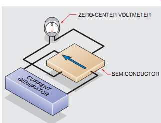
FIG. 26 Basic Hall generator.
THE CURRENT PATH IS CHANGED.
A VOLTAGE IS PRODUCED IN THE GENERATOR.
MAGNET
0 S CURRENT GENERATOR
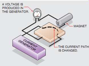
FIG. 27 The presence of a magnetic field causes
the Hall generator to produce a voltage.
CURRENT GENERATOR DIRECTION OF CURRENT CHANGES BECAUSE OF CHANGE OF MAGNETIC POLARITY.
POLARITY OF VOLTAGE CHANGES.
MAGNET
0 N
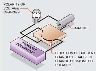
FIG. 28 If the magnetic field polarity changes, the polarity of the
voltage changes.
DC-AC clamp-on ammeters ( FIG. 25) use the Hall effect as the basic principle of operation.
The Hall effect was discovered by Edward H. Hall at Johns Hopkins University in 1879. Hall originally used a piece of pure gold to produce the Hall effect, but today a semiconductor material is used because it has better operating characteristics and is less expensive. The device is often referred to as a Hall generator. FIG. 26 illustrates the operating principle of the Hall generator. A constant current generator supplies a continuous current to the semiconductor chip. The leads of a zero-center voltmeter are connected across the opposite sides of the chip. As long as the current flows through the center of the semiconductor chip, no potential difference or voltage develops across the chip.
If a magnetic field comes near the chip ( FIG. 27), the electron path is distorted and the current no longer flows through the center of the chip. A volt age across the sides of the chip is produced. The voltage is proportional to the amount of current flow and the amount of current distortion. Since the current remains constant and the amount of distortion is proportional to the strength of the magnetic field, the voltage produced across the chip is proportional to the strength of the magnetic field.
If the polarity of the magnetic field were reversed ( FIG. 28), the current path would be distorted in the opposite direction, producing a volt age of the opposite polarity. Notice that the Hall generator produces a voltage in the presence of a magnetic field. It makes no difference whether the field is moving or stationary. The Hall effect can, therefore, be used to measure direct or alternating current.
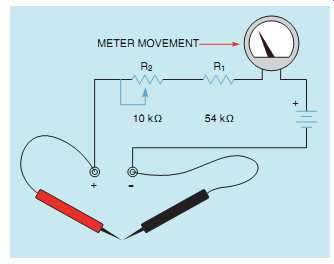 FIG. 29 Basic series ohmmeter.
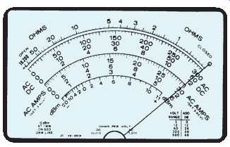
FIG. 30 Adjusting the ohmmeter to zero.
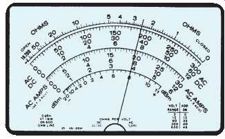
FIG. 31 Reading the ohmmeter.
THE OHMMETER
The ohmmeter is used to measure resistance. The common VOM (volt-ohm-milliammeter) contains an ohmmeter. The ohmmeter has the only scale on a VOM that is nonlinear. The scale numbers increase in value as they progress from right to left. There are two basic types of analog ohm meters, the series and the shunt. The series ohmmeter is used to measure high values of resistance, and the shunt type is used to measure low values of resistance. Regardless of the type used, the meter must provide its own power source to measure resistance. The power is provided by batteries located inside the instrument.
THE SERIES OHMMETER
A schematic for a basic series ohmmeter is shown in FIG. 29. It’s assumed that the meter movement has a resistance of 1000 ohm and requires a current of 50 µA to deflect the meter full scale.
The power source will be a 3-V battery. R1,a fixed resistor with a value of 54 k-O, is connected in series with the meter movement, and R2, a variable resistor with a value of 10 k-O, is connected in series with the meter and R1. These resistance values were chosen to ensure there would be enough resistance in the circuit to limit the current flow through the meter movement to 50 µA. If Ohm's law is used to compute the resistance needed (3 V/0.000050 A=60,000 O), it will be seen that a value of 60 k-O is needed. This circuit contains a total of 65,000 ohm (1000 [meter]+ 54,000+10,000). The circuit resistance can be changed by adjusting the variable resistor to a value as low as 55,000 O, however, to compensate for the battery as it ages and becomes weaker.
When resistance is to be measured, the meter must first be zeroed. This is done with the ohms adjust control, the variable resistor located on the front of the meter. To zero the meter, connect the leads ( FIG. 29) and turn the ohms-adjust knob until the meter indicates zero at the far right end of the scale ( FIG. 30). When the leads are separated, the meter will again indicate infinity resistance at the left side of the scale. When the leads are connected across a resistance, the meter will again go up the scale. Since resistance has been added to the circuit, less than 50 µA of current will flow, and the meter will indicate some value other than zero. FIG. 31 shows a meter indicating a resistance of 2.5 Ohm, assuming the range setting is Rx1.
Ohmmeters can have different range settings such as Rx1, Rx100, Rx1000, or Rx10,000. These different scales can be obtained by adding different values of resistance in the meter circuit and resetting the meter to zero. An ohmmeter should always be readjusted to zero when the scale is changed. On the R_1 setting, the resistance is measured straight off the resistance scale located at the top of the meter. If the range is set for Rx1000, however, the reading must be multiplied by 1000. The ohmmeter reading shown in FIG. 31 would be indicating a resistance of 2500 ohm if the range had been set for Rx1000. Notice that the ohmmeter scale is read backward from the other scales. Zero ohms is located on the far right side of the scale, and maximum ohms is located at the far left side. It generally takes a little time and practice to read the ohmmeter properly.
== DIGITAL METERS ==
DIGITAL OHMMETERS
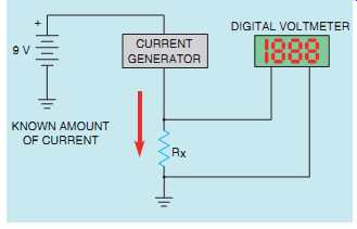
FIG. 32, a constant-current generator supplies a known amount of current
to a resistor, Rx. It will be assumed that the amount of current supplied
is…
Digital ohmmeters display the resistance in figures instead of using a meter movement. When using a digital ohmmeter, care must be taken to notice the scale indication on the meter. For example, most digital meters will display a K on the scale to indicate kilohms or an M to indicate megohms (kilo means 1000 and mega means 1,000,000). If the meter is showing a resistance of 0.200 K, it means 0.200x1000, or 200 Ohm. If the meter indicates 1.65M, it means 1.65x1,000,000, or 1,650,000 Ohm.
Appearance is not the only difference between analog and digital ohmmeters. Their operating principle is different also. Analog meters operate by measuring the amount of current change in the circuit when an unknown value of resistance is added. Digital ohmmeters measure resistance by measuring the amount of voltage drop across an unknown resistance. In the circuit shown in 1 mA. The voltage dropped across the resistor is proportional to the resistance of the resistor and the amount of current flow. For example, assume the value of the unknown resistor is 4700 O. The voltmeter would indicate a drop of 4.7 V when 1 mA of current flowed through the resistor. The scale factor of the ohmmeter can be changed by changing the amount of current flow through the resistor. Digital ohmmeters generally exhibit an accuracy of about 1%.
The ohmmeter, whether digital or analog, must never be connected to a circuit when the power is turned on. Since the ohmmeter uses its own internal power supply, it has a very low operating volt age. Connecting a meter to power when it’s set in the ohms position will probably damage or destroy the meter.
DIGITAL MULTIMETERS
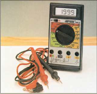
FIG. 33 Digital multimeter. Amprobe Instrument.
Digital multimeters have become increasingly popular in the past few years. The most apparent difference between digital meters and analog meters is that digital meters display their reading in discrete digits instead of with a pointer and scale. A digital multimeter is shown in FIG. 33. Some digital meters have a range switch similar to the range switch used with analog meters. This switch sets the full range value of the meter. Many digital meters have voltage range settings from 200 mV to 2000 V. The lower ranges are used for accuracy.
For example, assume it’s necessary to measure a voltage of 16 V. The meter will be able to make a more accurate measurement when set on the 20-V range than when set on the 2000-V range.
Some digital meters don’t contain a range set ting control. These meters are known as autoranging meters. They have a function control switch that permits selection of the electrical quantity to be measured, such as AC volts, DC volts, ohms, and so on. When the meter probes are connected to the object to be tested, the meter automatically selects the proper range and displays the value.
Analog meters change scale value by inserting or removing resistance from the meter circuit ( FIG. 7). The typical resistance of an analog meter is 20,000 ohm per volt for DC and 5000 ohm per volt for AC. If the meter is set for a full scale value of 60 V, there will be 1.2 MO of resistance connected in series with the meter if it’s being used to measure DC (60x20,000=1,200,000) and 300 k-O if it’s measuring AC (60x5000=300,000). The impedance of the meter is of little concern if it’s used to measure circuits that are connected to a high current source. For example, assume the voltage of a 480-V panel is to be measured with a multimeter that has a resistance of 5000 ohm per volt. If the meter is set on the 600-V range, the resistance connected in series with the meter is 3 MO (600x5000=3,000,000). This resistance will permit a current of 160 µA to flow in the meter circuit (480/3,000,000=0.000160). This 160 µA of current is not enough to affect the circuit being tested.
Now assume that this meter is to be used to test a 24-V circuit that has a current flow of 100 µA. If the 60-V range is used, the meter circuit contains a resistance of 300 k-O (60x5000=300,000). There fore a current of 80 µA will flow when the meter is connected to the circuit (24/300,000=0.000080).
The connection of the meter to the circuit has changed the entire circuit operation. This phenomenon is known as the loading effect.
Digital meters don’t have a loading effect.
Most digital meters have an input impedance of about 10 M-O on all ranges. The input impedance is the ohmic value used to limit the flow of current through the meter. This impedance is accomplished by using field effect transistors (FETs) and a volt age divider circuit. A simple schematic for such a circuit is shown in FIG. 34. Notice that the meter input is connected across 10 M-O of resistance regardless of the range setting of the meter.
If this meter is used to measure the voltage of the 24-V circuit, a current of 2.4 µA will flow through the meter. This is not enough current to upset the rest of the circuit, and voltage measurements can be made accurately.
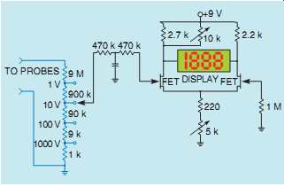
FIG. 34 Digital voltmeter.
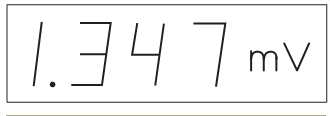
FIG. 35 Display indicates a voltage of 1.347 millivolts.
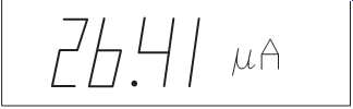
FIG. 36 Display indicates a current of 26.41 microamperes.
READING A DIGITAL METER
It would seem that reading a digital meter would be a simple matter of looking at the numbers on the display. This may not be the case, however. The reading on the display of autoranging digital meters, for example, may represent anything from ohms to megohms, or volts to millivolts. These meters usually display a notation beside the numerical digits to indicate the meter scale. FIG. 35 illustrates the display of a typical digital meter.
It shows the numbers 1.347 with a notation beside the numbers of mV, or millivolts. The actual meter reading is 1.347 millivolts or 0.001347 volts.
The display in FIG. 36 indicates a current of 26.41 µA. The µ symbol means micro or one millionth and the A means amps. The meter is indicating a current of 26.41 microamperes or 0.00002641 amps. It’s very important to pay attention to the notation symbols following the digits on the display of a digital meter.
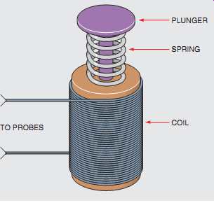
FIG. 37 Low-impedance voltage tester. TO PROBES PLUNGER SPRING COIL
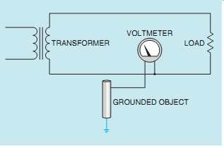
FIG. 38 High-impedance ground paths can produce misleading voltage reading.
VOLTMETER; LOAD TRANSFORMER; GROUNDED OBJECT
THE LOW-IMPEDANCE VOLTAGE TESTER
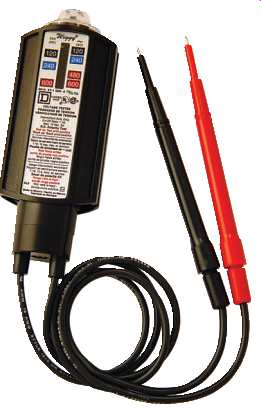
FIG. 39 Wiggins voltage tester (Square D).
Another device used to test voltage is often referred to as a voltage tester. This device does measure voltage, but it does not contain a meter movement or digital display. It contains a coil and a plunger.
The coil produces a magnetic field that is proportional to the amount of voltage to which the coil of the tester is connected. The higher the voltage, the stronger the magnetic field becomes. The plunger must overcome the force of a spring as it’s drawn into the coil ( FIG. 37). The plunger acts as a pointer to indicate the amount of voltage to which the tester is connected. The tester has an impedance of approximately 5000 ohm and can generally be used to measure voltages as high as 600 V. The low-impedance voltage tester has a very large current draw compared with other types of voltmeters and should never be used to test low-power circuits.
The relatively high current draw of the voltage tester can be an advantage when testing certain types of circuits, however, because it’s not susceptible to giving the misleading voltage readings caused by high-impedance ground paths or feedback voltages that affect other types of voltmeters. An example of this advantage is shown in FIG. 38.
A transformer is used to supply power to a load.
Notice that neither the output side of the transformer nor the load is connected to ground. If a high-impedance voltmeter measures between one side of the transformer and a grounded point, it will most likely indicate some amount of voltage.
That is because ground can act as a large capacitor and can permit a small amount of current to flow through the circuit created by the meter. This high impedance ground path can support only a few microamps of current flow, but it’s enough to operate the meter movement. If a voltage tester makes the same measurement, it won’t show a voltage because there cannot be enough current flow to attract the plunger. A voltage tester is shown in FIG. 39.
SUMMARY
• The d'Arsonval type of meter movement is based on the principle that like magnetic fields repel.
• The d'Arsonval movement operates only on DC current.
• Voltmeters have a high resistance and are designed to be connected directly across the power line.
• The steps to reading a meter are: A. Determine what quantity the meter is set to measure. B. Determine the full range value of the meter. C. Read the meter.
• Ammeters have a low resistance and must be connected in series with a load to limit the flow of current.
• Shunts are used to change the value of DC ammeters.
• AC ammeters use a current transformer to change the range setting.
• Clamp-on ammeters measure the flow of current by measuring the strength of the magnetic field around a conductor.
• Ohmmeters are used to measure the resistance in a circuit.
• Ohmmeters contain an internal power source, generally batteries.
• Ohmmeters must never be connected to a circuit that has power applied to it.
• Digital multimeters display their value in digits instead of a meter movement.
• Digital multimeters generally have an input impedance of 10 M-Ohm on all ranges.
• Digital ohmmeters measure resistance by measuring the voltage drop across an unknown resistor when a known amount of current flows through it.
• Low-impedance voltage testers are not susceptible to indicating a voltage caused by a high impedance ground or a feedback.
QUIZ:
1. To what is the turning force of a d'Arsonval meter movement proportional?
2. What type of voltage must be connected to a d'Arsonval meter movement?
3. A DC voltmeter has a resistance of 20,000 ohm per volt. What is the resistance of the meter if the range selection switch is set on the 250-V range?
4. What is the purpose of an ammeter shunt?
5. How is an ammeter connected into a circuit?
6. How is a voltmeter connected into a circuit?
7. An ammeter shunt has a voltage drop of 50 mV when 50 A of current flow through it. What is the resistance of the shunt?
8. What type of meter contains its own separate power source?
SOME PRACTICE PROBLEMS
MEASURING INSTRUMENTS
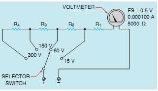
FIG. 40 -- The multirange voltmeter operates by connecting different
values of resistance in series with the meter movement.
1. A d'Arsonval meter movement has a full scale current value of 100 µA (0.000100 A) and a resistance of 5 k-O (5000 O). What size resistor must be placed in series with this meter to permit it to indicate 10 V full scale?
2. The meter movement described in question 1 is to be used to construct a multirange voltmeter. The meter is to have voltage ranges of 15 V, 60 V, 150 V, and 300 V ( FIG. 40). Find the values of resistors R1,R2,R3, and R4.
3. A meter movement has a full scale value of 500 µA (0.000500 A) and 50 mV (0.050 V). A shunt is to be connected to the meter that permits it to have a full scale current value of 2 A. What is the resistance of the shunt?
4. A digital voltmeter indicates a voltage of 2.5 V when 10 µA of current flows through a resistor.
What is the resistance of the resistor?
PRACTICAL APPLICATIONS
1. You are working in an industrial plant. You have a multimeter with the following voltage ranges: 30, 60, and 150. The meter states that it has a resistance of 5000 O/V. You need to measure a circuit that has a voltage of 277 V. How much resistance should be added in series with the meter to permit the 30-V range to have a full scale value of 300 V?