AMAZON multi-meters discounts AMAZON oscilloscope discounts
Thermal generating plants are designed and constructed to convert energy from fuel (coal, oil, gas, or radiation) into electric power. The actual conversion is accomplished by a turbine-driven generator. Thermal generating plants differ from industrial plants in that the nature of the product never changes. The plant will always produce electric energy. The things that may change are the fuel used (coal, oil, or gas) and environmental requirements. Many plants that were originally designed for coal were later converted to oil, converted back to coal, and then converted to gas. Environmental requirements have changed, which has required the construction of air and water emissions control systems.
Plant electrical systems should be designed to allow for further growth. Sizing of transformers and buses is at best a matter of guesswork. The plant electrical system should be sized at 5%-10% the size of the generating unit depending on the plant configuration and number of units at the plant site. The layout of a typical system is seen in FIG. 1.
1. Plant Auxiliary System
1.1 Selection of Auxiliary System Voltages
The most common plant auxiliary system voltages are 13,800, 6,900, 4,160, 2,400, and 480 V. The highest voltage is determined by the largest motor. If motors of 4,000 hp or larger are required, one should consider using 13,800 V. If the largest motor required is less than 4000 hp, then 4160 V should be satisfactory.
1.2 Auxiliary System Loads
Auxiliary load consists of motors and transformers. Transformers supply lower level buses which supply smaller motors and transformers which supply lower voltage buses. Generation plants built before 1950 may have an auxiliary generator that is connected to the main generator shaft. The auxiliary generator will supply plant loads when the plant is up and running.
1.3 Auxiliary System Power Sources
The power sources for a generating plant consist of one or more off-site sources and one or more on-site sources. The on-site sources are the generator and, in some cases, a black start diesel generator or a gas turbine generator which may be used as a peaker.
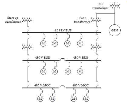
FIG. 1 Typical plant layout.
1.4 Auxiliary System Voltage Regulation Requirements
Most plants will not require voltage regulation. A load flow study will indicate if voltage regulation is required. Transformers with tap changers, static var compensators, or induction regulators may be used to keep plant bus voltages within acceptable limits. Switched capacitor banks and overexcited synchro nous motors may also be used to regulate bus voltage.
2. Plant One-Line Diagram
The one-line diagram is the most important document you will use. Start with a conceptual one-line and add detail as it becomes available. The one-line diagram will help you think about your design and make it easier to discuss with others. Do not be afraid to get something on paper very early and modify as you get more information about the design. Consider how the plant will be operated. Will there be a start-up source and a running source? Are there on-site power sources?
3. Plant Equipment Voltage Ratings
Establish at least one bus for each voltage rating in the plant. Two or more buses may be required depending on how the plant will be operated.
4. Grounded vs. Ungrounded Systems
A method of grounding must be determined for each voltage level in the plant.
4.1 Ungrounded
Most systems will be grounded in some manner with the exception for special cases of 120 V control systems which may be operated ungrounded for reliability reasons. An ungrounded system may be allowed to continue to operate with a single ground on the system. Ungrounded systems are undesirable because ground faults are difficult to locate. Also, ground faults can result in system overvoltage, which can damage equipment that is connected to the ungrounded system.
4.2 Grounded
Most systems 480 V and lower will be solidly grounded.
4.3 Low-Resistance Grounding
Low-resistance grounding systems are used at 2400 V and above. This system provides enough ground fault current to allow relay coordination and limits ground fault current to a value low enough to pre vent equipment damage.
4.4 High-Resistance Grounding
High-resistance grounding systems limit ground fault current to a very low value but make relay coordination for ground faults difficult.
5. Miscellaneous Circuits
5.1 Essential Services
Essential services such as critical control required for plant shutdown, fire protection, and emergency lighting should be supplied by a battery-backed inverter. This is equipment that must continue to operate after a loss of off-site power. Some of these loads may be supplied by an on-site diesel generator or gas turbine if a delay after loss of off-site power is acceptable.
5.2 Lighting Supply
Lighting circuits should be designed with consideration to emergency lighting to the control room and other vital areas of the plant. Consideration should be given to egress lighting and lighting requirements for plant maintenance.
6. DC Systems
The plant will require at least one DC system for control and operation of essential systems when off-site power is lost. The required operating time for the emergency equipment that will be operated from the DC systems must be established in order to size the batteries. The installation of a diesel generator may reduce the size of the battery.
6.1 125 V DC
A 125 V DC system is supplied for circuit breaker and protective relaying. The system voltage may collapse to close to zero during fault conditions and would not be capable of supplying relay control and breaker trip current when it is needed to operate.
6.2 250 V DC
A 250 V DC system may be required to supply turbine generator emergency motors such as turning gear motors and emergency lube oil motors.
7. Power Plant Switchgear
7.1 High-Voltage Circuit Breakers
High-voltage circuit breakers of 34.5 kV and above may be used in the switchyard associated with the generating plant, but are rarely used in a generating plant.
7.2 Medium-Voltage Switchgear
Medium-voltage breakers are 2.4-13.8 kV. Breakers in this range are used for large motors in the plant.
The most prevalent is 4.16 kV.
7.2.1 Medium-Voltage Air Circuit Breakers
Air circuit breakers were the most common type of breaker until about 1995. Due to large size and high maintenance requirements of air circuit breakers, they have been replaced by vacuum breakers.
7.2.2 Medium-Voltage Vacuum Circuit Breakers
Vacuum circuit breakers are the most common type of circuit breaker used in new installations. Vacuum circuit breakers are being used to replace air circuit breakers. Vacuum breakers are smaller and can pro vide additional space if the plant needs to be expanded to meet new requirements. Before using vacuum circuit breakers, a transient analysis study should be performed to determine if there is a need for surge protection. If required, surge protection can be supplied by the installation of capacitors and/or surge suppressors can be used to eliminate voltage surge problems.
7.2.3 Medium-Voltage SF6 Circuit Breakers
SF6 circuit breakers have the same advantages as vacuum circuit breakers but there is some environ mental concern with the SF6 gas.
7.3 Low-Voltage Switchgear
Low voltage is 600 V and below. The most common voltage used is 480 V.
7.3.1 Low-Voltage Air Circuit Breakers
Air circuit breakers are used in load centers that may include a power transformer. Air circuit breakers are used for motors greater than 200 hp and less than about 600 hp. Low-voltage circuit breakers are self contained in that fault protection is an integral part of the breaker. Low-voltage devices, which do not contain fault protection devices, are referred to as low-voltage switches. Low-voltage breakers may be obtained with various combinations of trip elements. Long time, short time, and ground trip elements may be obtained in various combinations.
Low-voltage breakers manufactured before 1970 will contain oil dashpot time delay trip elements.
Breakers manufactured after the mid-1970s until about 1990 will contain solid-state analog trip elements. Breakers manufactured after 1990 will contain digital trip elements. The digital elements provide much more flexibility.
A circuit that may be large enough for a load center circuit breaker but is operated several times a day should not be put on a load center circuit breaker. The circuit breaker would be put through its useful life in a very short time. A motor starter would be a better choice.
7.4 Motor Control Centers
Motor control centers are self-contained and may include molded case breakers or combination starters.
Molded case breakers are available as either magnetic or thermal-magnetic. The magnetic trip breakers are instantaneous trip only and the thermal-magnetic trip breakers are time delay with instantaneous trip. Magnetic breakers can be used with a contactor to make a combination starter. Time delay trip is provided by overload relays mounted on the contactor. Solid-state equipment is available to use in motor control centers and allows much greater flexibility.
7.5 Circuit Interruption
The purpose of a circuit breaker is to provide a method of interrupting the circuit either to turn the load on and off or to interrupt fault current. The first requirement is based on the full load current of the load. The second requirement is based on the maximum fault current as determined by the fault cur rent study. There is no relationship between the load current and the fault current. If modifications are made to the electric power system, the fault interrupting current requirement may increase. Failure to recognize this could result in the catastrophic failure of a breaker.
8. Auxiliary Transformers
8.1 Selection of Percent Impedance
The transformer impedance is always compromised. High transformer impedance will limit fault cur rent and reduce the required interrupting capability of switchgear and, therefore, reduce the cost. Low impedance will reduce the voltage drop through the transformer and therefore improve voltage regulation. A careful analysis using a load flow study will help in arriving at the best compromise.
8.2 Rating of Voltage Taps
Transformers should be supplied with taps to allow adjustment in bus voltage. Optimum tap settings can be determined using a load flow study.
9. Motors
9.1 Selection of Motors
Many motors are required in a thermal generating plant and range in size from fractional horsepower to several thousand horsepower. These motors may be supplied with the equipment they drive or they may be specified by the electrical engineer and purchased separately. The small motors are usually sup plied by the equipment supplier and the large motors specified by the electrical engineer. How this will be handled must be resolved very early in the project. The horsepower cut-off point for each voltage level must be decided. The maximum plant voltage level must be established. A voltage of 13.8 kV may be required if very large horsepower motors are to be used. This must be established very early in the plant design so that a preliminary one-line diagram may be developed.
9.2 Types of Motors
9.2.1 Squirrel Cage Induction Motors
The squirrel cage induction motor is the most common type of large motor used in a thermal generating plant. Squirrel cage induction motors are very rugged and require very little maintenance.
9.2.2 Wound Rotor Induction Motors
The wound rotor induction motor has a rotor winding which is brought out of the motor through slip rings and brushes. While more flexible than a squire cage induction motor, the slip rings and brushes are an additional maintenance item. Wound rotor motors are only used in special applications in a power plant.
9.2.3 Synchronous Motors
Synchronous motors may be required in some applications. Large slow-speed, 1800 rpm or less may require a synchronous motor. A synchronous motor may used to supply VARs and improve voltage regulation. If the synchronous motor is going to be used as a VAR source, the field supply must be sized large enough to over-excite the field.
9.2.4 Direct Current Motors
Direct current motors are used primarily on emergency systems such as turbine lube oil and turbine turning gear. Direct current motors may also be used on some control valves.
9.2.5 Single-Phase Motors
Single-phase motors are fractional horsepower motors and are usually supplied with the equipment.
9.2.6 Motor Starting Limitations
The starting current for induction motors is about six times full load current. This must be taken into account when sizing transformers and should be part of the load flow analysis. If the terminal voltage is allowed to drop too low, below 80%, the motor will stall. Methods of reduced voltage starting are avail able, but should be avoided if possible. The most reliable designs are the simplest.
10. Main Generator
The turbine generator will be supplied as a unit. The size and characteristics are usually determined by the system planners as a result of system load requirements and system stability requirements.
10.1 Associated Equipment
10.1.1 Exciters and Excitation Equipment
The excitation system will normally be supplied with the generator.
10.2 Electronic Exciters
Modern excitation systems are solid state and, in recent years, most have digital control systems.
10.3 Generator Neutral Grounding
The generator neutral is never connected directly to ground. The method used to limit the phase to ground fault current to a value equal to or less than the three-phase fault current is determined by the way the generator is connected to the power system. If the generator is connected directly to the power system, a resistor or inductor connected between the neutral of the generator and ground will be used to limit the ground fault current. If the generator is connected to the power system through a transformer in a unit configuration, the neutral of the generator may be connected to ground through a distribution transformer with a resistor connected across the secondary of the transformer. The phase-to-ground fault current can be limited to 5-10 A using this method.
10.4 Isolated Phase Bus
The generator is usually connected to the step-up transformer through an isolated phase bus. This separated phase greatly limits the possibility of a phase-to-phase fault at the terminals of the generator.
11. Cable
Large amounts of cable are required in a thermal generating plant. Power, control, and instrumentation cable should be selected carefully with consideration given to long life. Great care should be given in the installation of all cable. Cable replacement can be very expensive.
12. Electrical Analysis
All electrical studies should be well-documented for use in plant modifications. These studies will be of great value in evaluating plant problems.
12.1 Load Flow
A load flow study should be performed as early in the design as possible even if the exact equipment is not known. The load flow study will help in getting an idea of transformer size and potential voltage drop problems.
A final load flow study should be performed to document the final design and will be very helpful if modifications are required in the future.
12.2 Short-Circuit Analysis
Short-circuit studies must be performed to determine the requirements for circuit breaker interrupting capability. Relay coordination should be studied as well.
12.3 Surge Protection
Surge protection may be required to limit transient overvoltage caused by lightning and circuit switching. A surge study should be performed to determine the needs of each plant configuration. Surge arrestors and/or capacitors may be required to limit transient voltages to acceptable levels.
12.4 Phasing
A phasing diagram should be made to determine correct transformer connections. An error here could prevent busses from being paralleled.
12.5 Relay Coordination Studies
Relay coordination studies should be performed to ensure proper coordination of the relay protection system. The protective relay system may include overcurrent relays, bus differential relays, transformer differential relays, voltage relays, and various special function relays.
13. Maintenance and Testing
A good plant design will take into account maintenance and testing requirements. Equipment must be accessible for maintenance and provisions should be made for test connections.
14. Start-Up
A start-up plan should be developed to ensure equipment will perform as expected. This plan should include insulation testing. Motor starting current magnitude and duration should be recorded and relay coordination studies verified. Voltage level and load current readings should be taken to verify load flow studies. This information will also be very helpful when evaluating plant operating conditions and problems.