AMAZON multi-meters discounts AMAZON oscilloscope discounts
GOALS:
• describe the torque, speed, rotation, speed
regulation, and control characteristics of a cumulative compound-wound DC motor.
• perform the preliminary test for the proper installation of a cumulative compound motor.
• connect DC compound motors.
• describe the characteristics of a differential compound-wound DC motor.
• describe the characteristics of a cumulative compound-wound DC motor.
Compound-wound motors are used whenever it is necessary to obtain speed regulation and torque characteristics not obtainable with either a shunt or a series motor. Because many drives need a fairly high starting torque and a constant speed under load, the compound wound motor is suitable for these applications. Some of the industrial applications include drives for passenger and freight elevators, stamping presses, rolling mills, and metal shears.
The compound motor has a normal shunt winding and a series winding on each field pole.
As in the compound-wound DC generator, the series and shunt windings may be connected in long shunt, as shown in FIG. 1(A), or short shunt, shown in FIG. 1(B).
When the series winding field is connected to aid the shunt winding field, the machine is a cumulative compound motor. When the series field opposes the shunt field, the machine is a differential compound motor. Using Fleming's left-hand rule for electromagnets, it can be seen that the two windings will either reinforce each other or try to cancel each other (FIG. 2).
TORQUE
The operating characteristics of a cumulative compound-wound motor are a combination of those of the series motor and the shunt motor. When a load is applied, the increasing current through the series winding increases the field flux. As a result, the torque for a given current is greater than it would be for a shunt motor. However, this flux increase causes the speed to decrease to a lower value than in a shunt motor. A cumulative compound-wound motor develops a high torque with any sudden increase of load. It is best suited for operating varying load machines such as punch presses.
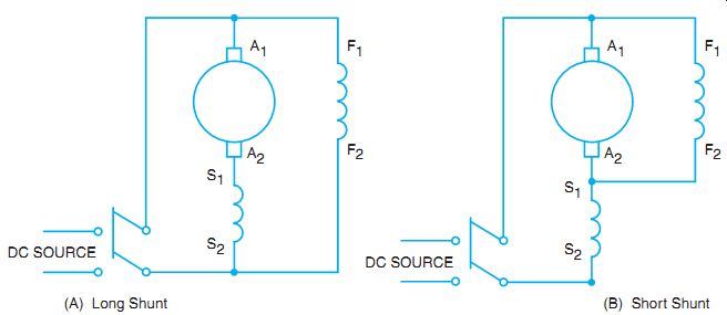
FIG. 1 Motor field connections. (A) Long Shunt (B) Short Shunt
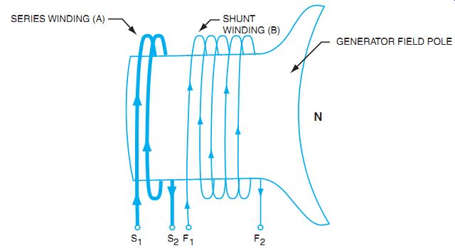
FIG. 2 Compound field windings.
SPEED
Unlike a series motor, the cumulative compound motor has a definite no-load speed and will not build up to destructive speeds if the load is removed.
Speed Control
The speed of a cumulative compound motor can be controlled by using resistors in the armature circuit to reduce the applied voltage. When the motor will be used for installations where the rotation must be frequently reversed, such as in elevators, hoists, and railways, the controller should have voltage dropping resistors and switching arrangements to accomplish reversal.
This was the general mode of control for older installations of DC motors. Now, most of the controllers use electronics to accomplish the same effect.
Electronic Speed Control
A block diagram approach to the electronic speed control of a DC motor is presented in FIG. 3. The AC line is rectified by a full-wave bridge to supply pulsating DC to the shunt field at a steady value. The input is shown as a single-phase AC source, but the input may be a three-phase AC source, especially for larger motors. The DC supplied to the armature and the series field is controlled by a silicon-controlled rectifier (SCR) or other solid-state electronics such as a MOSFET (metal-oxide semiconductor field-effect transistor). By adjusting the firing time of the semiconductor, either more or less of the DC voltage available can be applied to the armature. If a low amount of DC voltage is applied, the torque is low and the resultant speed is low. If the solid-state device is fired early in the waveform and allowed to conduct for most of the cycle, then a larger amount of voltage is applied to the armature, more current results, and torque increases to spin the armature at a higher speed. Speeds below rated motor speed are produced by lowering the amount of voltage applied to the armature while keeping the shunt field steady; if higher than normal speed is needed, the shunt field can be weakened. Most speed controls have some type of feedback to sense the armature current, compare it to the set speed, and adjust the electronic conduction control to compensate for varying mechanical loads to keep the motor speed regulated. (For more details, see Guide 6.)
Speed Regulation
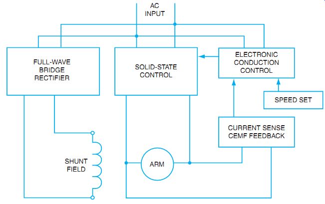
FIG. 3 Block diagram of electronic speed control for a DC motor.
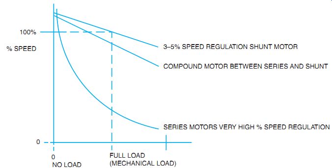
FIG. 4 Graph of speed regulation of shunt, compound, and series-connected
DC motors.
The speed regulation of a cumulative compound-wound motor is inferior to that of a shunt motor and superior to that of a series motor. It is a compromise between a series motor and a shunt motor, as seen in FIG. 4.
The graph in FIG. 4 shows that the percent of speed regulation of a compound- wound DC motor is lower than that of a shunt motor but higher than that of a series motor.
The speed versus torque curves presented in Figure 2-2 show the relationship between the shunt, series, and compound motor. The series has the highest torque at the lowest speed, but the speed regulation is very poor. The shunt motor has less torque at higher loads, but the speed regulation is very good. The compound motor has characteristics of both, in that the torque and speed regulation characteristics are in between the shunt and the series motor.
ROTATION
The rotation of a compound-wound motor can be reversed by changing the direction of the current in the field circuits or the armature circuit (FIG. 5). Because the series field coils must also be reversed if the shunt field is reversed, it is conventional to reverse the current in the armature only.
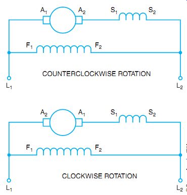
FIG. 5 Standard connections for compound motors.
PRELIMINARY TEST FOR CUMULATIVE COMPOUNDING
When a motor is first connected, it is important to determine the continuity of the shunt field circuit. In addition, for a compound-wound motor, the proper magnetic polarity of the shunt and series field must be determined. Standardized tests determine these conditions. For example, when a compound motor is ready to be placed into operation, a double check for proper compounding is necessary. It must be verified that the series field is aiding the shunt field flux. Connecting the compound motor is referred to as cumulative compounding. If this is not done, the motor may start at light load under the influence of the shunt field. As the load increases, the series field becomes more powerful. If the series field is an opposite polarity from the shunt field, the stator field becomes weaker. Eventually the series field becomes more dominant, and it may suddenly reverse the direction of rotation of the motor.
The following test verifies field polarity. With no load on the motor, connect the motor as a shunt motor only, without placing the series field in the circuit. Momentarily start the motor and note the direction of rotation. Keep track of which motor lead markings are connected to which line leads. Now connect the motor as a series motor, without the shunt field.
Momentarily start the motor. Do not let it run without a mechanical load. Again, be sure to note which series field leads are connected to which line leads. If the motor turns the same direction each time, reconnect the shunt field to the original line leads. If not, reverse the shunt field leads so that both series and shunt motor connections cause the same direction of rotation. This establishes cumulative compounding.
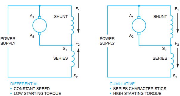
FIG. 6 Magnetic polarities of compound motors.
DIFFERENTIAL
• CONSTANT SPEED
• LOW STARTING TORQUE CUMULATIVE
• SERIES CHARACTERISTICS
• HIGH STARTING TORQUE
Differential Compounding
Almost 0% speed regulation can be obtained with a differentially compounded motor. When a motor is connected as a differential compound machine, the series field opposes the shunt field so that the field flux is decreased as a load is applied (FIG. 6). As a result, the speed remains substantially constant with an increase in load. With overcompounding, a slight increase in speed is possible with an increase in load. This speed characteristic is achieved only with a loss in the rate at which torque increases with load.
Because the field decreases with a load increase, a differential compound motor has a tendency for load instability. When starting a differential motor, it is recommended that the series field be shorted because the great starting current in this field may overbalance the shunt field and cause the motor to start in the opposite direction.
A differential machine is connected and tested on installation using the same procedure outlined for a cumulative compound motor. For the differential motor, however, the series windings should be connected in the opposite direction from that of the shunt winding. Do not exceed the load on the nameplate, or reversal of direction may occur as noted in the description of cumulative compounding.
SUMMARY
The DC compound motor is used where a compromise is needed between the series and the shunt motor. The compound motor has better speed characteristics than the series motor and better torque characteristics than the shunt motor. The motor can be connected so that the shunt field and the series fields are in the same direction. This is the cumulative connection. You should perform a test to be sure the motor is connected as intended. The cumulative connection reacts differently than the differential connection. Many DC motors are now driven by electronic drives. The same basic concepts are used to control speed and direction.
QUIZ
1. Circle the letter for each of the following statements that applies to a cumulative compound-wound DC motor.
a. The speed regulation of a cumulative compound-wound DC motor is better than that of a shunt motor.
b. The speed of a cumulative motor has a no-load limit.
c. The speed of the motor decreases more for a given increase in load than does a differential motor.
d. A cumulative motor has less torque than a shunt motor of the same hp rating for a given increase in armature current.
e. The speed regulation of a cumulative motor is better than that of a series motor.
f. A cumulative motor develops a high torque with a sudden increase of load.
g. To reverse the direction of rotation, the current in either the armature or the shunt field must be reversed.
h. A cumulative motor is connected so that the series flux aids the shunt winding flux.
i. When installing a cumulative compound-wound motor, the direction of rotation should be the same when testing the motor for operation either as a series motor or a shunt motor.
2. Circle the letter for each of the following statements that applies to a differential compound-wound DC motor.
a. A differential motor is used in applications where an essentially constant speed at various loads is required.
b. The starting torque for a differential motor is higher than that of a cumulative motor.
c. The motor may reverse its direction of rotation if started under a heavy load.
d. This motor develops a speed instability because the flux field decreases with a load increase.
e. When starting a differential motor, the shunt field should be shorted because of the great starting current.
3. Arrange the following steps numerically in the correct sequence to test for the proper connections to operate a cumulative compound-wound motor. Place the step number in the space provided, starting with number 1.
____ a. If rotation is in direction opposite to that desired, reverse the series field leads.
____ b. Start motor as a shunt motor and observe rotation.
____ c. Connect only the series field, start motor, and immediately shut it down while noting direction of rotation.
____ d. Connect the shunt field circuit; the motor is now ready for operation.