AMAZON multi-meters discounts AMAZON oscilloscope discounts
GOALS:
• describe the construction of a three-phase AC motor, listing the main components of this type of motor.
• identify the following items, and explain their importance to the operation of a three-phase AC induction motor: rotating stator field, synchronous speed, rotor-induced voltages, speed regulation, percent slip, torque, starting current, no-load power factor, full-load power factor, reverse rotation, and speed control.
• calculate motor speed and percent slip.
• reverse a squirrel-cage motor.
• describe why a motor draws more current when loaded.
• draw diagrams showing the dual-voltage connections for 240/480-volt motor operation.
• explain motor nameplate information.
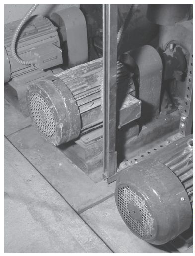
FIG. 1 Three-phase motors used for a pumping application.
OPERATING CHARACTERISTICS
The three-phase AC induction motor is relatively small in physical size for a given horsepower rating when compared with other types of motors. The squirrel-cage induction motor has very good speed regulation under varying load conditions. Because of its rugged construction and reliable operation, the three-phase AC induction motor is widely used for many industrial applications (FIG. 1).
CONSTRUCTION DETAILS
The three-phase AC induction motor normally consists of a stator, a rotor, and two end shields housing the bearings that support the rotor shaft.
A minimum of maintenance is required with this type of motor because
• The rotor windings are shorted to form a squirrel cage.
• There are no commutator or slip rings to service (compared to the DC motor).
• There are no brushes to replace.
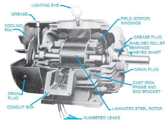
FIG. 2 Cutaway view of construction and features of a typical three-phase
explosion-proof motor.
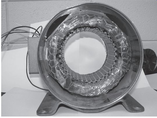
FIG. 4 Stator of three-phase motor.
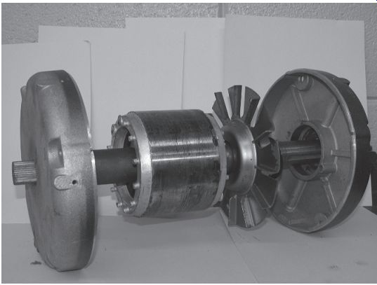
FIG. 3 Squirrel-cage rotor with internal fan and end bells of induction
motor.
The motor frame is usually made of cast steel. The stator core is pressed directly into the frame. The two end shields housing the bearings are bolted to the cast steel frame. The bearings that support the rotor shaft are either sleeve bearings or ball bearings. FIG. 2 is a cutaway view of an assembled motor. FIG. 3 illustrates the main parts of a three-phase AC induction motor.
Stator--A typical stator contains a three-phase winding mounted in the slots of a laminated steel core (FIG. 4). The winding itself consists of formed coils of wire connected so that three single-phase windings are spaced 120 electrical degrees apart. The three separate single-phase windings are then connected, usually internally, in either wye or delta. Three or nine leads from the three-phase stator windings are brought out to a terminal box mounted on the frame of the motor for single- or dual-voltage connections.
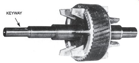
FIG. 5 Squirrel-cage rotor for an induction motor.
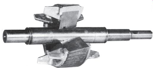
FIG. 6 Cutaway view of a squirrel-cage rotor.
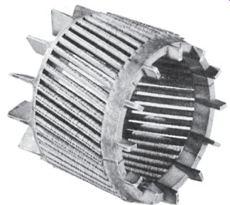
FIG. 7 Squirrel-cage form for an induction motor.
Rotor
The revolving part of the motor consists of steel punchings or laminations arranged in a cylindrical core (Figures 5, 6, and 7). Copper or aluminum bars are mounted near the surface of the rotor. The bars are brazed or welded to two copper end rings to form a short circuit for the rotor bars. In some small squirrel-cage induction motors, the bars and end rings are cast in one piece from aluminum.
FIG. 5 shows such a rotor. Note that fins are cast into the rotor to circulate air and cool the motor while it is running. Note also that the rotor bars between the rings are skewed at an angle to the faces of the rings. Because of this design, the running motor is quieter and smoother in operation. A keyway is visible on the left end of the shaft. A pulley or load shaft coupling can be secured using this keyway.
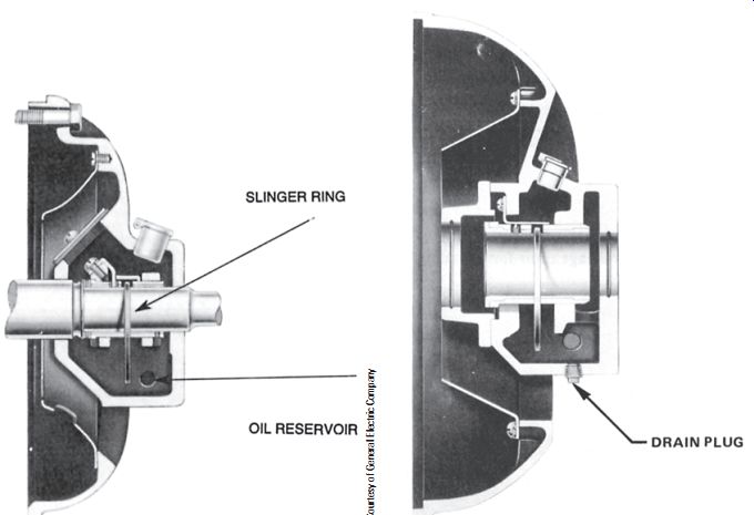
FIG. 8 Sleeve-bearing end shield for an open polyphase motor.

FIG. 9 Sleeve-bearing end shield for a polyphase induction motor.
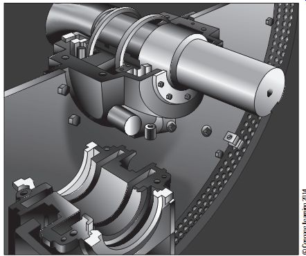
FIG. 10 Partially assembled sleeve bearing for a totally enclosed 1250
hp motor.
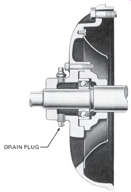
FIG. 11 Ball-bearing end shield for an open polyphase motor.
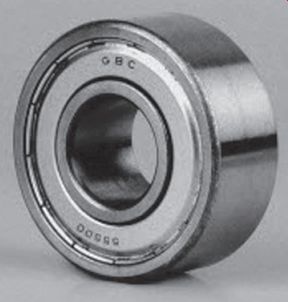
FIG. 12 Cutaway section of a single row ball bearing.
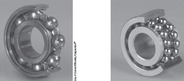
FIG. 13 Simple sealed-type of ball bearing.
FIG. 14 Double-row ball bearing.
Shaft Bearings
Typical sleeve bearings are shown in FIG. 8 and FIG. 9. The inside walls of the sleeve bearings are made of a babbitt metal that provides a smooth, polished, and long-wearing surface for the rotor shaft. A large, oversized oil slinger ring fits loosely around the rotor shaft and extends down into the oil reservoir. This ring picks up and slings oil on the rotating shaft and bearing surfaces. Two oil rings are shown in FIG. 10. This lubricating oil film minimizes friction losses. An oil inspection cup on the side of each end shield enables maintenance personnel to check the level of the oil in the sleeve bearing.
Figures 11, 12, 13, and 14 illustrate ball bearing units. In many motors, ball bearings are used instead of sleeve bearings. Grease rather than oil is used to lubricate ball bearings.
This type of bearing usually is two-thirds full of grease at the time the motor is assembled. Special fittings are provided on the end bells so that a grease gun can be used to apply additional lubricant to the ball bearing units at periodic intervals.
When lubricating roller bearings, remove the bottom plug so that the old grease is forced out. Consult the manufacturer's specifications for the motor for the lubricant grade recommended, the lubrication procedure, and the bearing loads.
PRINCIPLE OF OPERATION OF A SQUIRREL-CAGE MOTOR
As stated in the previous discussion of stator construction, the slots of the stator core contain three separate single-phase windings. When three currents 120 electrical degrees apart pass through these windings, a rotating magnetic field results. This field travels around the inside of the stator core. The speed of the rotating magnetic field depends on the number of stator poles and the frequency of the power source. This speed is called the synchronous speed and is determined by the following formula:
RPM = 120 × f p 120 × 60 6
= = 1200 RPM RPM = Synchronous speed f = Hertz (frequency) p = Number of stator poles per phase
Example 1: If a three-phase AC induction motor has six poles on the stator winding and is connected to a three-phase, 60-hertz source, then the synchronous speed of the revolving field is 1200 revolutions per minute (RPM).
As this magnetic field rotates at synchronous speed, it cuts the copper bars of the rotor and induces voltages in the bars of the squirrel-cage winding. These induced voltages set up currents in the rotor bars, which in turn create a field in the rotor core. This rotor field reacts with the stator field to cause a twisting effect, or torque, which turns the rotor. The rotor always turns at a speed slightly less than the synchronous speed of the stator magnetic field. This means that the stator magnetic field will always cut the rotor bars. If the rotor were to turn at the same speed as the stator field, the stator field would not cut the rotor bars and there would be no induced voltage or torque.
Speed Regulation and Percent Slip
The squirrel-cage induction motor has very good speed regulation characteristics (the ratio of difference in speed from no load to full load). Speed performance is measured in terms of percent slip. The synchronous speed of the rotating field of the stator is used as a reference point. Recall that the synchronous speed depends on the number of stator poles and the operating frequency. Because these two quantities remain constant, the synchronous speed also remains constant. If the speed of the rotor at full load is deducted from the synchro nous speed of the stator field, the difference is the number of revolutions per minute that the rotor slips behind the rotating field of the stator. The value is expressed as percent slip according to the following formula:
Percent slip = Synchronous speed - Rotor speed Synchronous speed
× 100
Example 2: If the three-phase AC induction motor used in Example 1 has a synchro nous speed of 1200 RPM and a full-load speed of 1140 RPM, find the percent of slip.
Synchronous speed (Example 1) = 1200 RPM Full-load rotor speed = 1140 RPM Percent slip = 5% Percent slip = 1200 - 1140 1200 × 100 Percent slip = 60 1200 × 100 = 0.05 × 100 Percent slip = Synchronous speed - Rotor speed Synchronous speed
× 100
For a squirrel-cage induction motor, as the value of percent slip decreases toward 0%, the speed performance of the motor is improved. The average range of percent slip for squirrel-cage induction motors is 2% to 6%.
FIG. 15 shows a speed curve and a percent slip for a squirrel-cage induction motor operating between no load and full load. The rotor speed at no load slips behind the synchro nous speed of the rotating stator field just enough to create the torque required to overcome friction and windage losses at no load. As a mechanical load is applied to the motor shaft, the rotor tends to slow down. This means that the stator field (turning at a fixed speed) cuts the rotor bars a greater number of times in a given period. The induced voltages in the rotor bars increase, resulting in more current in the rotor bars and a stronger rotor field. A greater magnetic reaction between the stator and rotor fields exists, which causes a stronger twisting effect, or torque. This also increases stator current taken from the line. The motor is able to handle the increased mechanical load with very little decrease in the speed of the rotor.
Typical slip-torque curves for a squirrel-cage induction motor are shown in FIG. 16.
The torque output of the motor in pound-feet (lb-ft) increases linearly with an increase in the value of percent slip as the mechanical load is increased to the point of full load. Beyond full load, the torque curve bends and finally reaches a maximum point called the breakdown torque.
If the motor is loaded beyond this point, there will be a corresponding decrease in torque until the point is reached where the motor stalls. However, all induction motors must have some slip in order to function. Starting torque is not shown, but is approximately 300% of running torque for a generic AC motor.
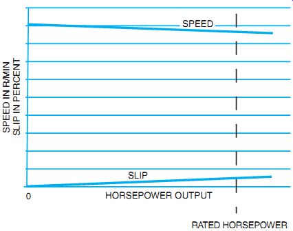
FIG. 15 Speed curve and percent slip curve.
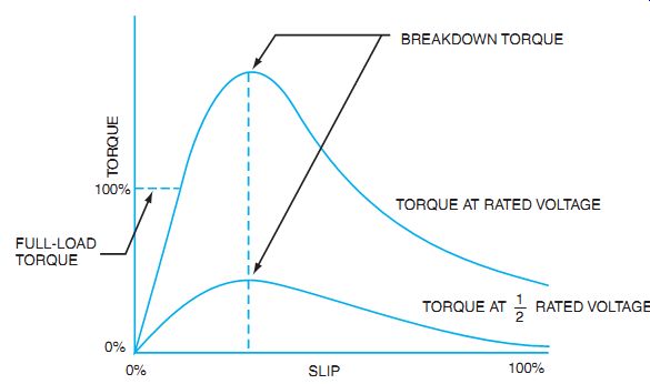
FIG. 16 Slip-torque curves for a running squirrel-cage motor.
Starting Current When a three-phase AC induction motor is connected across the full line voltage, the starting surge of current momentarily reaches as high as 400% to 1000% or more of the rated full-load current. At the moment the motor starts, the rotor is at a standstill. At this instant, therefore, the stator field cuts the rotor bars at a faster rate than when the rotor is turning.
This means that there will be relatively high induced voltages in the rotor, which cause heavy rotor current. The resulting input current to the stator windings is high at the instant of starting. Because of this high starting current, starting protection rated as high as 300% of the rated full-load current for nontime-delay fuses is provided for squirrel-cage induction motor installations.
Most squirrel-cage induction motors are started at full voltage. If there are any questions concerning starting large motors at full voltage, the electric utility company should be consulted. In the event that the feeders and protective devices of the electric utility are unable to handle the large starting currents, reduced voltage starting circuits must be used with the motor.
Power Factor
The power factor of a squirrel-cage induction motor is poor at no-load and light-load conditions. At no load, the power factor can be as low as 15% lagging. However, as load is applied to the motor, the power factor increases. At the rated load, the power factor may be as high as 85% to 90% lagging.
The power factor at no load is low because the magnetizing component of input current is a large part of the total input current of the motor. When the load on the motor is increased, the in-phase current supplied to the motor increases, but the magnetizing component of current remains practically the same. This means that the resultant line current is more nearly in phase with the voltage and the power factor is improved when the motor is loaded, compared with an unloaded motor.
FIG. 17 shows the increase in power factor from a no-load condition to full load. In the no-load diagram, the in-phase current (IW) is small when compared to the magnetizing cur rent IM; thus, the power factor is poor at no load. In the full-load diagram, the in-phase current has increased while the magnetizing current remains the same. As a result, the angle of lag of the line current decreases and the power factor increases.
Reversing Rotation
The direction of rotation of a three-phase induction motor can be readily reversed. The motor rotates in the opposite direction if any two of the three line leads are reversed (FIG. 18). The leads are reversed at the motor.
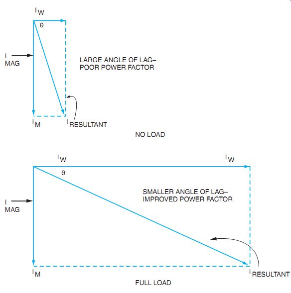
FIG. 17 Power factor at no load and full load.
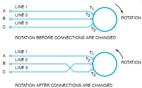
FIG. 18 Reversing rotation of an induction motor.
Speed Control
A squirrel-cage induction motor has almost no speed variations without external controls.
Recall that the speed of the motor depends on the frequency of the three-phase source and the number of poles of the stator winding.
The frequency of the supply line is usually 60 hertz in the United States, and is maintained at this value by the local power utility company. Because the number of poles in the motor is also a fixed value, the synchronous speed of the motor remains constant. As a result, obtaining a range of speed without changing the applied frequency is impossible. It can be controlled by a variable frequency AC electronic drive system or by changing the number of poles using external controllers. See Guide 14 on electronic frequency control.
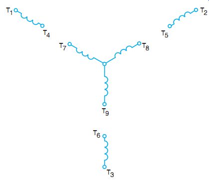
FIG. 19 Method of identifying terminal markings.
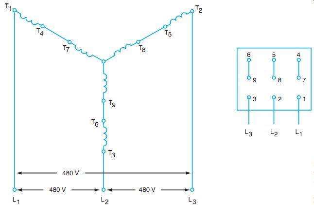
FIG. 20 480-volt wye connection; coils are connected in series.
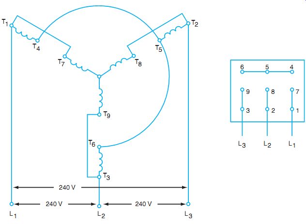
FIG. 21 240-volt wye connection; coils are connected in parallel.
INDUCTION MOTORS WITH DUAL-VOLTAGE CONNECTIONS
Many three-phase AC induction motors are designed to operate at two different voltage ratings.
For example, a typical dual-voltage rating for a three-phase motor is 240/480 volts.
FIG. 19 shows a typical wye-connected stator winding that can be used for either 240 volts, three phase, or 480 volts, three phase. Each of the three single-phase windings consists of two coil windings. Nine leads are brought out externally from this type of stator winding.
These leads, identified as leads 1 to 9, end in the terminal box of the motor. To mark the terminals, start at the upper-left terminal T1 and proceed in a clockwise direction in a spiral toward the center, marking each lead as indicated in the figure.
FIG. 20 shows the connections required to operate a motor from a 480-volt, three phase source. The two coils of each single-phase winding are connected in series. FIG. 21 shows the connections to permit operation from a 240-volt, three-phase source.
Wye- or Star-Connected Motors
If the lead identifications of a nine-lead (dual-voltage), three-phase, wye-connected motor have been destroyed, the electrician must re-identify them before connecting the motor to the line.
The following method may be used. First, identify the internally connected common point by checking for continuity between three of the leads as in FIG. 22(A).
Then identify the three other sets of coils by continuity between two leads at a time, shown in FIG. 22(B). Assign T7, T8, and T9 to any of the three leads of the permanent star-connected coils (A). Apply the lower-rated line voltage for the motor to T7, T8, and T9, and operate to check the direction of rotation. Disconnect line voltage and connect one of the undetermined coils to T7. Reconnect power, leaving the lines on T7, T8, and T9. If the coil is correctly connected and is the proper coil, the voltage should be about 1.5 times the line voltage between the loose end and the other two lines. Be careful of line voltage.
If the correct coil is selected but reversed, the voltage between the loose end and the other two leads will be about 58% of the line voltage. If the wrong coil is selected, the voltage differences between the loose end and the other two line leads will be uneven. See FIG. 22(C).
When the readings are even and approximately 1.5 times the line voltage, mark the lead connected to T7 as T4 and other end of the coil as T1.
Perform the same tests with another coil connected to T8. Mark these leads T5 and T2.
Perform the same test with the last coil connected to T9 to identify the T3 and T6 leads.
Connect L1 to T1, L2 to T2, L3 to T3, T4 to T7, T5 to T8, T6 to T9, and then operate the motor. The motor should operate quietly in the same direction as before.
Delta-Connected Motors
Another connection pattern for three-phase motors is the delta-connected motor. It is so named because the resulting schematic pattern looks like the Greek letter delta ( Δ). A method of identifying and connecting these leads is necessary because this pattern is different from the star- or wye-connected motor.
Properly connecting the leads of a delta-connected, three-phase, dual-voltage motor presents a problem if the lead markings are destroyed.
First, the electrician must determine whether the motor is delta connected or star connected. Both motors have nine leads if they are dual-voltage motors. However, the delta- connected motor has three sets of three leads that have continuity, and the star-connected motor has only one set of three.
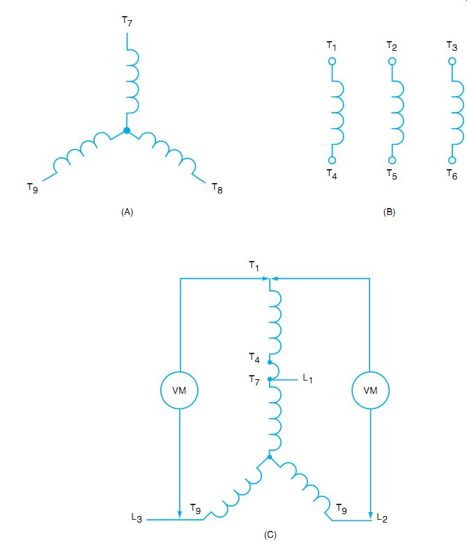
FIG. 22 Wye- or star-connected motor. (A) Internal star-point connection.
(B) Coil group lead marking. (C) Checking for proper coil lead markings on
wye- connected, dual-voltage motor.
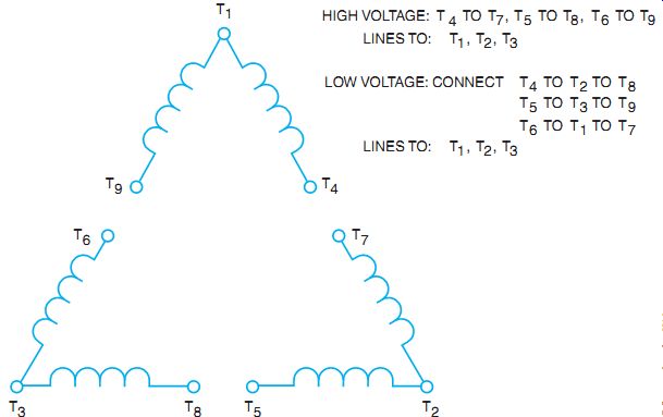
FIG. 23 Nine leads of a delta-connected, three-phase, dual-voltage motor.
After it is determined that the motor is delta connected, a sensitive ohmmeter is needed to find the middle of each group of three leads. The ohm values are low when using the DC power of an ohmmeter, so use care in identifying the center of each coil group. Label the center of each group T1, T2, and T3, respectively. Using masking tape, temporarily label the other leads of the T1 group as T4 and T9 (see FIG. 23).
Temporarily mark the ends of the T2 group as T5 and T7, and mark the ends of the T3 group as T6 and T8.
Connect the lower motor voltage rating using lines 1, 2, and 3 to T1, T4, and T9. The other coils will have induced voltage, so be careful not to touch the other loose leads to each other or to yourself! Disconnect the power and connect the lead marked T4 to T7. Reconnect the power as before and read the voltage between T1 and T2. If the markings are correct, the voltage should be about twice the applied line voltage. If it reads about 1.5 times the line voltage, reconnect T4 to the lead marked T5. If the voltage T1 to T2 then goes to line voltage, reconnect T9 to T7, thereby reversing both coils. When the voltage T1 to T2 equals twice the applied line voltage, mark the leads connected together as T4 from the T1 group connected to T7 of the T2 group.
Now use the third coil group. Leave the lower line voltage connected to the first group as before. Test and connect the leads so that when T9 is connected to a lead of the third group, the T1-to-T3 voltage is twice the applied line voltage. Mark the lead connected to T9 as T6 and the other end of the coil group as T8.
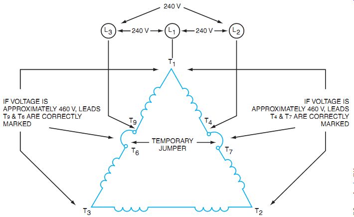
FIG. 24 Illustration of voltage tests used to determine correct lead
markings on a delta motor.
To double-check, disconnect the line lead from T9 and reconnect it to T7; disconnect the line lead from T1 and reconnect it to T2; disconnect the line lead from T4 and reconnect it to T5. The motor should run in the same direction as before. If it does not, recheck the lead markings.
To check further, move the line leads from T7 to T8, from T5 to T6, and from T2 to T3.
Start the motor. Rotation should be the same as in the previous steps. Be careful! Voltage is induced into other windings. (See FIG. 24.)
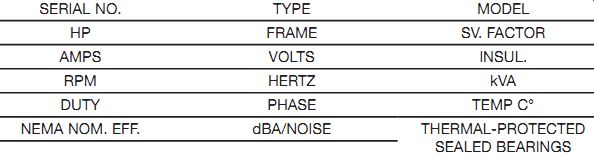
FIG. 25 Typical motor nameplate.
MANUFACTURER'S NAME INDUCTION MOTOR MADE IN U.S.A.
MOTOR NAMEPLATES
Motor nameplates provide information vital to the proper selection and installation of the motor. Most useful data given on the nameplate refer to the electrical characteristics of the motor. Given this information and using the National Electrical Code, the electrician can determine the conduit, wire, and starting and running protection sizes. (The NEC provides minimum requirements.)
The design and performance data on the nameplate are useful to maintenance personnel.
The information is vital for the fast and proper replacement of the motor, if necessary.
For a better understanding of the motor, typical information found on motor nameplates is described here (FIG. 25):
• The manufacturer's name can be found on the nameplate.
• Type identifies the type of the enclosure. This is the manufacturer's coded identification system.
• Serial number is the specific motor identification. This is the individual number assigned to the motor, similar to a social security number for a person. It is kept on file by the manufacturer.
• The model number is an additional manufacturer's identification, commonly used for ordering purposes.
• Frame size identifies the measurements of the motor.
• Service factor (or SF). An SF of 1.0 means the motor should not be expected to deliver more than its rated horsepower. The motor will operate safely if it is run at the rated horsepower times the SF, maximum. Common SFs are 1.0 to 1.15. It is recommended that the motor not be run continuously in the SF range. This may shorten the life expectancy of the insulation system.
• Amperes means the current drawn from the line when the motor is operating at rated voltage and frequency at the fully rated nameplate horsepower.
• Volts should be the value measured at the motor terminals and for which the motor is designed.
• The class of insulation refers to the insulating material used in winding the motor stator. For example, in a Class B system, the maximum operating temperature is 130°C (266°F); for Class F, it is 155°C (311°F); and for Class H, it is 180°C (356°F). This is the maximum temperature of the motor coil.
• RPM means the speed in revolutions per minute when all other nameplate conditions are met.
• Hertz is the frequency of the electric power system for which the motor is designed.
Performance will be altered if it is operated at other frequencies.
• Duty is the cycle of operation at which the motor can safely operate. "Continuous" means that the motor can operate fully loaded 24 hours a day. If "intermediate" is shown, a time interval also appears. This means the motor can operate at full load for the specified period. The motor should then be stopped and allowed to cool before starting again.
• Ambient temperature specifies the maximum surrounding air temperature at which the motor can operate to deliver the rated horsepower.
• Phase indicates the number of voltage phases at which the motor is designed to operate.
• kVA is a code letter that indicates the locked rotor kVA per horsepower. This is used to determine starting equipment and protection for the motor. A code letter table is found in NEC 430.7(B).
• Efficiency is expressed as a percentage. This value is found on standard motors as well as "premium efficiency" motors.
• Noise. Some motors are designed for low noise emission. The noise level given on the nameplate is measured in "dBA" units of sound.
• Manufacturer's notes list specific features of the motors, such as "thermal protected" and/ or "scaled bearings."
• Design letter is a manufacturer's coded letter for the motor design that affects operating characteristics. Five standard classifications are designs A, B, C, D, and E. Each design has a special speed versus torque curve and is used for different applications. Design B is the most common.
ALTITUDE
Manufacturers' guarantees for standard motor ratings are usually based on operation at any altitude up to 3300 ft. Motors suitable for operation at an altitude higher than 3300 ft above sea level are of special design and/or have a different insulation class. For example, standard motors with an SF of 1.15 may be operated up to an altitude of 9900 ft by reducing the SF. At an altitude of 9900 ft, the SF would be 1.00. It may be necessary to derate the motor or use a larger frame size.
SUMMARY
Three-phase AC induction motors use a squirrel-cage winding in the rotor. There are no electrical connections to the rotor, but current is induced into the rotor windings by electromagnetic induction. The squirrel-cage winding produces a magnetic field that is pushed and pulled by the stator magnetic field.
The rotor is supported by a steel shaft that must rotate. The shaft is allowed to rotate with the application of different types of bearings and various lubrications. Synchronous speed, speed regulation, and percent slip are all calculations used in determining the speed of the rotor.
Motor electrical characteristics such as power factor and starting current are related to the electrical design of the motor.
If motor lead markings are destroyed, the leads can be remarked according to the procedures outlined in this guide. Motor nameplate data are critical information to be used when ordering replacement motors. Some nameplate information is essential for proper replacement of the operating characteristics, and other data are used to size the electrical supply and the motor protection.
QUIZ
A. Answer the statements and questions in items 1 through 8.
1. List the essential parts of a squirrel-cage induction motor. _
2. State two advantages of using a squirrel-cage induction motor.
3. State two disadvantages of a squirrel-cage induction motor.
4. List the two factors that determine the synchronous speed of an induction motor.
5. Explain how to reverse the direction of rotation of a three-phase AC induction motor.
6. A four-pole, 60-hertz, three-phase AC induction motor has a full-load speed of 1725 RPM. Determine the synchronous speed of this motor.
7. What is the percent slip of the motor described in question 6?
8. Why is the term squirrel-cage applied to this type of three-phase induction motor?
B. Select the correct answer for the statements in items 9 through 14, and place the corresponding letter in the space provided.
9. Who or what determines whether large induction motors may be started at full voltage across the line?
a. maximum motor size
b. rated voltage
c. the power company
d. Department of Building and Safety
10. The power factor of a three-phase AC induction motor operating unloaded is _
a. the same as with full load.
b. very poor.
c. very good.
d. average.
11. The power factor of a three-phase AC induction motor operating with a full load ____
a. improves from no load.
b. decreases from no load.
c. remains the same as at no load.
d. becomes 100%.
12. The squirrel-cage induction motor is popular because of its characteristics of _
a. high percent slip.
b. low percent slip.
c. simple, rugged construction.
d. good speed regulation.
13. The speed of a squirrel-cage induction motor depends on _
a. voltage applied.
b. frequency and number of poles.
c. field strength.
d. current strength.
14. Synchronous speed (RPM) is calculated using the formula
a. p = 120 × f RPM
b. RPM = 120 × f p
c. RPM = 120 × p f
d. RPM = 120 × f p
C. Draw the following connection diagrams.
15. Show the connection arrangement for the nine terminal leads of a wye-connected, three-phase motor rated at 240/480 volts for operation at 480 volts, three phase.
16. Show the connection arrangement for the nine terminal leads of a wye-connected, three-phase motor rated at 240/480 volts for operation at 240 volts, three-phase.