AMAZON multi-meters discounts AMAZON oscilloscope discounts
GOALS:
• list the parts of a DC shunt motor.
• draw the connection diagrams for series shunt and compound motors.
• define torque and tell what factors affect the torque of a DC shunt motor.
• describe counter-EMF (CEMF) and its effects on current input.
• describe the effects of an increased load on armature current, torque, and speed of a DC shunt motor.
• list the speed control, torque, and speed regulation characteristics of a DC shunt motor.
• make DC motor connections.
The production of electrical energy and its conversion to mechanical energy in electric motors of all types is the basis of industrial productivity. Very basic DC motor principles are given in Electricity 1.
CONSTRUCTION FEATURES
Conventional DC motors closely resemble DC generators in construction features. In fact, it is difficult to identify them by appearance alone. A motor has the same two main parts as a generator--the field structure and the armature assembly consisting of the armature core, armature winding, commutator, and brushes. Some general features of a DC motor are shown in Fig. 1.
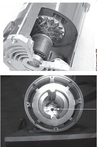
Fig. 1 (A) DC motor armature with commutator bars. (B) Permanent-magnet
DC motor with rotor and carbon brush connections.
The Field Structure
The field structure of a motor has at least two pairs of field poles, although motors with four pairs of field poles are also used, as shown in Fig. 2(A). A strong magnetic field is provided by the field windings of the individual field poles. The magnetic polarity of the field system is arranged so that the polarity of any particular field pole is opposite to that of the poles adjacent to it.
The Armature
The armature of a motor is a cylindrical iron structure mounted directly on the motor shaft, as shown in Fig. 2(B). In DC motors, the armature is the rotating component of the motor.
Armature windings are embedded in slots in the surface of the armature and terminate in segments of the commutator. Current is fed to these windings on the rotating armature by carbon brushes that press against the commutator segments. This current in the armature windings sets up a magnetic field in the armature that reacts with the magnetic field of the field poles. These magnetic effects are used to develop torque, which causes the armature to turn (Fig. 3). The commutator changes the direction of the current in the armature conductors as they pass across poles of opposite magnetic polarity. Continuous rotation in one direction results from these reversals in the armature current.
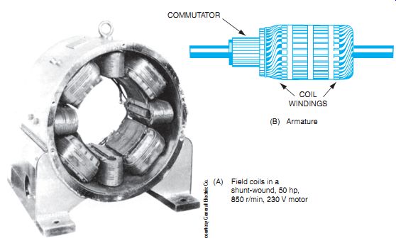
Fig. 2 Field structure and armature assembly of a motor. (B) Armature
(A) Field coils in a shunt-wound, 50 hp, 850 r/min, 230 V motor
Fig. 4 shows a cutaway view of a DC motor available with horsepower ratings ranging from 25.0 hp to 1000 hp.
By using the right-hand rule for motors, as illustrated in Fig. 5, you can determine which direction a current-carrying conductor will move when placed in a magnetic field. This is the principle of all motor action. The first finger represents the direction of the stator flux, as magnetic lines travel north to south. The center finger represents the direction of the electron current in the conductor placed within the magnetic field. The thumb represents the thrust of the conductor as it tries to move out of the magnetic field. As shown in Fig. 3, the coils of the armature are spaced around the rotor, and the rotor conductors are connected to the commutator segments. Because the coils of wire on the armature (rotor) have current flow through them, the magnetic field thus created in the rotor conductors reacts with the stationary field (stator), and the conductors will move according to the right-hand rule for motors. The conductors of the rotor that are directly adjacent to the stator pole pieces have the maximum rotor current and therefore the most magnetic interaction with the main magnetic poles.
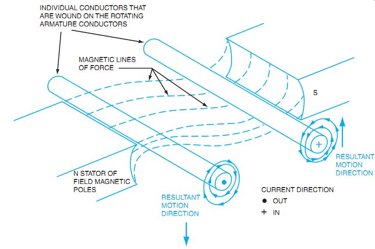
Fig. 3 Torque, or force direction, on a current-carrying conductor in
a magnetic field.
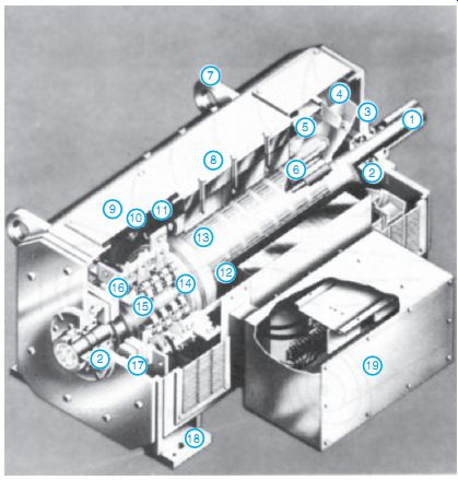
Fig. 4 Assembled 23 hp DC motor.
1. Main shaft
2. Bearings
3. Grease "meter"
4. Ventilating fan
5. Armature banding
6. Armature equalizer coil assembly
7. Lifting lugs
8. Frame
9. Inspection plate
10. Main field coil
11. Commutating coils
12. Main field coil
13. Armature
14. Commutator connections to armature turns
15. Commutator
16. Brushholder
17. Brushholder yoke
18. Mounting feet
19. Terminal conduit box
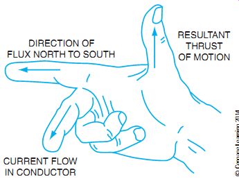
Fig. 5 Right-hand rule for motors using electron flow.
TYPES OF DC MOTORS
Shunt, series, compound, and permanent magnet motors are all widely used. The schematic diagrams for each type of motor are shown in Fig. 6. The selection of the type of motor to use is based on the mechanical requirements of the applied load. A shunt motor has the field circuit connected in shunt (parallel) with the armature, whereas a series motor has the armature and field circuits in series. A compound motor has both a shunt and a series field winding. A permanent magnet motor only has armature connections.
MOTOR RATINGS
DC motors are rated by their voltage, current, speed, and horsepower output. The number and methods of connection for the armature and field also dictate motor operating characteristics.
TORQUE
The rotating force at the motor shaft produced by the interaction of the magnetic fields of the armature and the field poles is called torque. As the magnitude of the torque increases, the twisting force of the shaft increases. Torque is defined as the product of the force in pounds and the radius of the shaft or pulley in feet.
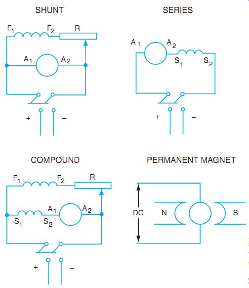
Fig. 6 Schematic diagrams that show motor connections. SERIES SHUNT COMPOUND
PERMANENT MAGNET
For example, a motor that produces a tangential force of 120 pounds at the surface of the shaft 2 in. in diameter or 1 in. in radius has a torque of 10 foot-pounds (ft-lbs).
Torque = Force × Radius = 120 lbs × 1/12 ft = 10 ft-lbs
Torque in a motor depends on the magnetic strengths of the field and the armature.
The torque increases along with the armature current and, consequently, the strength of the armature magnetic field increases.
Another example is shown in Fig. 7. If a V-belt drive has a pulling force at the radius of a motor pulley of 25 pounds, and the pulley surface is 1 ft from the center of the motor shaft, the motor torque is the product of the radius (measured in ft) and the pulling force (measured in pounds). The torque is usually measured in foot-pounds, the standard measure for torque.
For small motors, the torque may be measured in ounce-inches (oz-in). The same principle is used, but the ounce-inch measurement must be divided by 192 (12 inches × 16 ounces) to get the equivalent foot-pounds.
It is necessary to distinguish between the torque developed by a motor when operating at its rated speed and the torque developed at the instant the motor starts. Certain types of motors have high torque at rated speed but poor starting torque.
The many types of loads that can be applied to motors mean that the torque characteristic must be considered when selecting a motor for a particular installation.
ROTATION
The direction of the armature rotation of a DC motor depends on the direction of the current in the field circuit and the armature circuit (Fig. 8). To reverse the direction of rotation, the current direction in either the field or the armature must be reversed.
Reversing the power supply leads causes both the armature and the field to become reversed, as shown in Fig. 9. To determine the direction of the conductor movement, use the right-hand rule for motors, as shown in Fig. 5. The first finger indicates the direction of the flux (north to south), the center finger indicates the direction of the current flow (negative to positive), and the thumb indicates the direction of the resultant thrust.
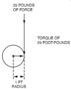
Fig. 7 Torque is measured as the pulling force at some
distance from the center of the motor shaft. If the force is 25 pounds and the distance is 1 ft from the center of the shaft, the motor torque is 25 ft-lbs.
STARTING CURRENT AND CEMF
The starting current of a DC motor is much higher than the running current while the motor is operating at its rated speed. At the instant power is applied, the armature is motionless and the armature current is limited only by the very low armature circuit wire resistance. As the motor builds up to its rated speed, the current input decreases until the motor reaches its rated speed.
At this point, the armature current stops decreasing and remains constant.
Factors other than armature wire resistance also limit the current. Fig. 10 illustrates a demonstration that shows the "generator" action (CEMF) within a motor that accounts for the decrease in current with a speed increase.
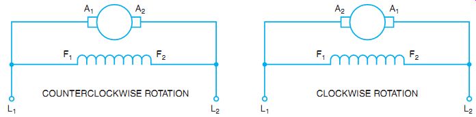
Fig. 8 Standard connections for shunt motors.
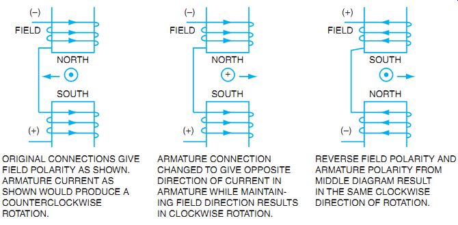
Fig. 9 Reversing either the armature connections or the field connections
causes the direction of armature rotation to change; changing both connections
results in the same direction of rotation. ORIGINAL CONNECTIONS GIVE FIELD
POLARITY AS SHOWN.
ARMATURE CURRENT AS SHOWN WOULD PRODUCE A COUNTERCLOCKWISE ROTATION.
ARMATURE CONNECTION CHANGED TO GIVE OPPOSITE DIRECTION OF CURRENT IN ARMATURE WHILE MAINTAIN ING FIELD DIRECTION RESULTS IN CLOCKWISE ROTATION.
REVERSE FIELD POLARITY AN ARMATURE POLARITY FROM MIDDLE DIAGRAM RESULT IN THE SAME CLOCKWISE DIRECTION OF ROTATION.
In Fig. 10, a DC motor and a lamp (each with the same voltage rating) are connected in parallel to the DC source. A zero-center ammeter connected in the circuit indicates the amount and direction of the current to the motor. When the line switch is open (A), there is no current in any part of the circuit. When the switch is closed (B), the lamp lights instantly and the ammeter registers high current to the motor. The motor current decreases as the motor speed increases and remains constant when the motor reaches its rated speed. The instant the switch is opened, the ammeter deflection reverses. The lamp continues to light but grows dimmer as the motor speed falls.
Two conclusions can be drawn from this demonstration:
• A DC motor develops an induced voltage while rotating.
• The direction of the induced voltage is opposite to that of the applied voltage and for this reason is called counter-EMF (CEMF).
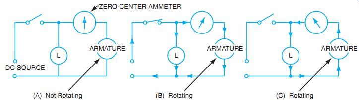
Fig. 10 Demonstration of CEMF.
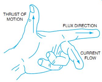
Fig. 11 Left-hand rule for generators.
The amount of voltage generated within a spinning armature depends on the speed of the rotation and the strength of the magnetic field. Just as in any generator, the left-hand rule for generators applies, as shown in Fig. 11.
Even though the armature is being caused to spin through motor action, the act of spinning a coil of wire within a magnetic field causes it to act like a generator. The thumb represents the direction of thrust of the moving conductor, and the first finger represents the direction of the main stator field magnetic flux. Now the first finger represents the direction of the induced current flow within the armature conductors, which is counter to the applied current. This counter-induced potential is CEMF. The induced current flow is smaller in magnitude than the applied current flow from the voltage source. The difference between the applied current flow and the counter-induced current is the differential current.
As the torque, or twisting effort, rotates the armature, the conductors of the armature cut the main field magnetic flux, as in a generator. This action induces a voltage into the armature windings that opposes line voltage.
The production of CEMF in a DC motor accounts for the changes in current to a motor armature at different speeds. When there is no current in the circuit, the motor armature is motionless and the CEMF is zero. The starting current is very high because only the ohmic resistance of the armature limits the current. As the armature starts to rotate, the CEMF increases and the line current decreases. When the speed stops increasing, the value of the CEMF approaches the value of the applied voltage but is never equal to it. The value of the voltage that actually forces current through the motor is equal to the difference between the applied voltage and the CEMF. At rated speed, this voltage differential just maintains the motor at constant speed, as shown in Fig. 12.
When a mechanical load is then applied to the motor shaft, both the speed and CEMF decrease. However, the voltage differential increases and causes an increase of input current to the motor. Any further increase in mechanical load produces a proportional increase in input current (Fig. 13).
The increase in motor current due to an increase in mechanical load also can be justified in terms of the torque. Because torque depends on the strength of the magnetic field of the armature, which, in turn, depends on the armature current, any increase in mechanical load requires an increase in the armature current, more load, slower speed, higher differential, and more current.
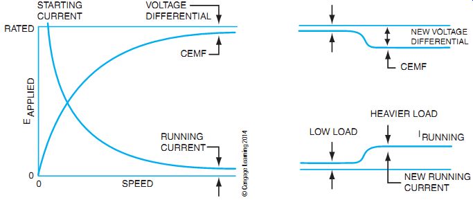
Fig. 12 Effects of CEMF on the armature current.
Fig. 13 Effects of CEMF and I_armature when the load is increased.
Because the starting current may be many times greater than the rated current under full load, large DC motors must not be connected directly to the power line for start-up. The heavy current surges produce excessive line voltage drops that may damage the motor. The maximum branch-circuit fuse size for any DC motor is based on the full-load running current of the motor. Therefore, starters for DC motors generally limit the starting current to 150% of the full-load running current.
ARMATURE REACTION
Armature reaction occurs in DC motors and is caused by the stator magnetic field being distorted, or altered, in reaction to the armature magnetic field. The armature reaction is actually a bending of the motor magnetic field so that the brushes are no longer aligned with the neutral magnetic plane of the motor. If the brushes are not in alignment with this magnetic plane, the current conducted to the armature does not split equally in the armature conductors and therefore causes a voltage difference at the brushes. This causes sparking where the brush meets the commutator. In a motor with a constant load, the brushes can be shifted back into the neutral plane to reduce sparking.
The brushes are shifted in the direction opposite to the rotation. If the motor has a varying load, the neutral plane will be constantly shifting. To counteract the effects of the field distortion, some motors are designed with interpoles or commutating poles. These poles are connected in series with the armature circuit. Every change in armature current that would tend to distort the magnetic field is counteracted by the interpole magnetic field or commutating windings (refer to Fig. 2).
SPEED CONTROL AND SPEED REGULATION
The terms speed control and speed regulation should not be used interchangeably. The meaning of each is entirely different. Speed regulation refers to a motor's capability to maintain a certain speed under varying mechanical loads from no load to full load. It is expressed as a percent.
The formula used is
Percent speed regulation =
No-load speed - Full-load speed Full-load speed
* 100
Using this formula, you can determine that a motor that holds a constant speed between no load and full load has a 0% speed regulation.
Speed control refers to changing the motor speed intentionally by means of external control devices. This is done in a variety of ways and is not a result of the design of the motor.
Speed Control
DC motors are operated below normal speed by reducing the voltage applied to the armature circuit. Resistors connected in series with the armature may be used for voltage reduction, or electronic speed control is used to reduce the voltage applied to the armature circuit. When the armature voltage is reduced while keeping the field current constant, the CEMF is too high, and no current flows to the rotor. The rotor torque is reduced, and the speed slows (Fig. 13). The speed of a DC motor can also be brought below its rated speed by varying the voltage applied to the entire motor. However, this method is not used because there is a loss of torque along with the reduction in speed.
A DC motor may be operated above its rated speed by reducing the strength of the stator field flux. A system is used to reduce the field current and, in turn, the field flux.
Although it seems reasonable that a reduction in field flux reduces the speed, the speed actually increases because the reduction of flux reduces the CEMF and permits the applied voltage to increase the armature cur rent. The speed continues to increase until the increased torque is balanced by the opposing torque of the mechanical load. When the field flux is reduced while keeping the armature voltage constant, the CEMF in the armature drops (Fig. 14). As a result, there is a larger voltage differential, which causes an increase in armature current.
This develops more torque to increase the speed of the motor (Fig. 15).
Caution: Because motor speed increases with a decrease in field flux, the field circuit of a motor should never be opened when the motor is operating, particularly when it is running freely without a load. An open field may cause the motor to rotate at speeds that are dangerous to both the machine and to the personnel operating it. For this reason, some motors are protected against excessive speed by a "no field release" feature. This device disconnects the motor from the power source if the field circuit opens.
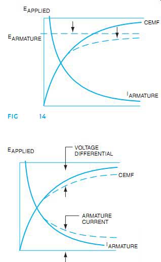
Fig. 14 To reduce speed, reduce the armature voltage while keeping the
field current constant.
Fig. 15 To increase speed, reduce the field current while keeping the armature voltage constant.
THE SHUNT MOTOR
Two factors are important when selecting a motor for a particular application: (1) the variation of the speed with a change in load and (2) the variation of the torque with a change in load.
A shunt motor is basically a constant speed device. If a load is applied, the motor tends to slow down. The slight loss in speed reduces the CEMF and results in an increase of the armature current. This action continues until the increased current produces enough torque to meet the demands of the increased load. As a result, the shunt motor reaches a state of stable equilibrium because a change of load always produces a reaction that adapts the power input to the change in load.
The basic circuit for a shunt motor is shown in Fig. 16(A). Note that only a shunt field winding is shown. Fig. 16(B) shows the addition of a series winding to counteract the effects of armature reaction. From the standpoint of a schematic diagram, Fig. 16(B) looks like a compound motor. However, this type of motor is not considered a compound motor because the commutating winding is not wound on the same pole as the field winding, and the series field has only a few turns of wire in series with the armature circuit. As a result, the operating characteristics are those of a shunt motor. This is so noted on the nameplate of the motor by the terms compensated shunt motor or stabilized shunt motor.
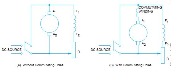
Fig. 16 Shunt motor connections. (A) Without Commutating Poles (B) With
Commutating Poles
Speed Control
A DC shunt motor has excellent speed control. To operate the motor above its rated speed, reduce the field current and field flux. To operate below rated speed, reduce the voltage applied to the armature circuit.
Electronic speed control systems are used extensively. The principles of control are the same as the old manual controls. Speeds above normal are achieved by reducing the field voltage electronically, and speeds below normal reduce the voltage applied to the armature.
(For more detail on electronic speed control, see Guide 6 on speed control.) Rotation The direction of armature rotation may be changed by reversing the direction of current in either the field circuit or the armature circuit. For a motor with a simple shunt field circuit, it may be convenient to reverse the field circuit lead. If the motor has a series winding, or an interpole winding to counteract armature reaction, the same relative direction of current must be maintained in the shunt and series windings. For this reason, it is always safer to reverse the direction of just the armature current.
Torque
A DC shunt motor has high torque at any speed. At start-up, a DC shunt motor develops 150% of its rated torque if the starting controller is capable of withstanding the heating effects of the current. For very short periods of time, the motor can develop 350% of full-load torque, if necessary.
Speed Regulation
The speed regulation of a shunt motor drops from 5% to 10% from the no-load state to full load.
As a result, a shunt motor is superior to the series DC motor, but is inferior to a compound wound DC motor (see Guides 2 and 3). Fig. 17 shows a typical DC motor with horsepower ratings ranging from 1 hp to 5 hp.
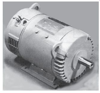
Fig. 17 DC motor, 1 hp to 5 hp.
PERMANENT MAGNET MOTORS
A variation on the DC shunt motor principle is the permanent magnet (PM) motor.
Two varieties are available. One style of PM motor uses a permanently magnetized material such as Alnico or ceramic magnets mounted in the stator to provide a constant magnetic field. The rotor is supplied with DC through a brush and commutator system. The result is similar to a DC shunt type motor, but it has a very linear speed/ torque curve.
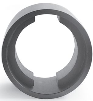
Fig. 18 DC permanent magnet stator. Courtesy of Bodine Electric Company
Another type of PM motor uses the PMs mounted in the rotor. Because DC is still supplied to the motor, commutation must be provided to properly magnetize the stator in relation to the rotor for rotational torque. The commutator segments are actually connected to the stator windings, and a set of sliding contacts on the rotor provides the proper electrical connection from the DC source to the proper commutator segments on the stator. This type of PM motor can be produced in larger horsepower models than the PM stator types. PM motors are generally smaller than 5 hp. Fig. 18 compares the physical size of a PM motor to a shunt motor of similar horsepower.
The DC permanent magnet motor is a popular motor where battery power provides the DC for the motor power. Small motors used for electrical drives in the automobile and motors such as trolling motors are good examples of PM motors. Rare-earth magnetic materials, such as samarium-cobalt and neodymium, have made the permanent magnets more powerful and allowed the size of PM motors to increase in horsepower to more than 15 hp. The torque-to weight ratio and the horsepower-to-weight ratio make these motors a popular choice for mobile vehicles where horsepower is needed with light weight. The operating characteristics of these motors resemble the characteristics of a separately excited shunt motor. The speed curve is dependent on the armature field current.
If a motor is not providing rotational torque, the problem could be that the magnets have lost some of the original magnetic strength. Another problem that can occur is the demagnetization of the PM material. This can happen when the motors are running in one direction and then are quickly reversed under power. Some control circuits provide protection from quick reversals; others compensate for this problem by applying a small voltage during reversing.
BRUSHLESS DC MOTORS
Instead of using mechanical commutation to supply a field and power to the rotor, electronics can be used to switch the stator field. The rotor uses a PM so that no direct power is supplied to the rotor. To switch the power supply to the field windings, sensing devices must be used to deter mine rotor movement. As the rotor speed increases or decreases, the sensor relays the information to the electronic switching supply. The electronic supply constantly adjusts to provide the proper level of voltage to the proper stator poles to maintain speed and direction (see Fig. 19).
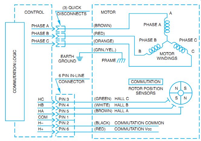
Fig. 19 Brushless DC motor control schematic.
SUMMARY
The DC shunt motor uses the shunt field as the main magnetic field in the stator. The shunt field is made up of many turns of small wire and is connected, or shunted, across the armature. The shunt field may have a series-connected control that adjusts the amount of current to the field. The principle of the DC motor relies on the concept of commutation. This commutator and brush connection always keep the direction of the current and the direction of the magnetic field consistent. The speed and the current to the rotor are inversely proportional. If the rotor is spinning faster, more CEMF is produced and less voltage differential, and therefore less armature current is produced. DC motors are used in a variety of styles for different purposes. Many variations of the shunt motor are used in specialized applications.
QUIZ
A. Select the correct answer for each of the following statements, and place the corresponding letter in the space provided.
1. DC motors are rated in ____
a. voltage, frequency, current, and speed.
b. voltage, current, speed, and torque.
c. voltage, current, and horsepower.
d. voltage, current, speed, and horsepower.
2. The generator effect in a motor produces a ____
a. high power factor.
b. high resistance.
c. CEMF.
d. reduced line voltage.
3. A DC motor draws more current with a mechanical load applied to its shaft because the_
a. CEMF is reduced with the speed.
b. voltage differential decreases.
c. applied voltage decreases.
d. torque depends on the magnetic strength.
4. The direction of rotation of a compound interpole motor may be reversed by reversing the direction of current flow through the _
a. armature.
b. armature or field circuit.
c. armature, interpoles, and series field.
d. shunt field.
5. The speed of a DC motor may be reduced below its rated without losing torque by reducing the voltage at the _
a. motor.
b. series field.
c. armature.
d. armature and field.
6. Advantages of DC motors include _
a. simplicity in construction.
b. speed control above and below base speed.
c. excellent torque and speed control.
d. horsepower for size.
B. Complete the following statements:
7. The twisting force exerted on the shaft of a motor is called and is due to the magnetic field interaction of the and ____.
8. Field interpoles connected in series with the armature circuit of a motor help counteract the effects of ___.
9. As a DC motor comes up to its rated speed, its armature current (decreases, remains the same, increases). (Circle the correct answer.)
10. The main factor controlling the armature current of a DC shunt motor operating at rated speed is the_.