AMAZON multi-meters discounts AMAZON oscilloscope discounts
[Note: various equations, denoted by "e." are not yet avail., but coming soon.]
1. Stray Currents in Distribution Systems
Electrical shock hazards can exist in many situations where there is no direct contact with any electrical conductors or equipment. This Section will discuss some of the hazards which are produced by electrical utility distribution systems. As with other power systems, distribution systems are designed to be safe, and to be in accordance with codes and standards whose purpose is to enforce safe design practices. Nonetheless, as these systems cover wide areas and are subject to a nearly infinite variety of conditions, serving all manner of loads for many human purposes, it is inevitable that safety hazards will exist. There are a variety of distribution systems in the world, with different voltages, grounding configurations, numbers of conductors, and so forth. This Section in particular addresses mostly the multigrounded neutral system prevalent in North America. Further information on other systems may be found in Mitolo (2009b).
Stray currents, sometimes called objectionable currents are part of the same phenomenon called stray voltage. Electric shocks to humans are documented in an EPRI technical brief on swimming pools. A detailed description of stray voltages caused by the multigrounded neutral system and their effects on both humans and farm animals is found in the USDA handbook (USDA, 1991). These can cause injuries to humans and farm animals in a similar manner to step and touch potentials in substations, only in the home and farm environment. Accidents to humans typically result from shock hazards at swimming pools, bathtubs, basements, and other wet locations.
These have led to the development of the ground fault current interrupter (GFCI).
Accidents to farm animals are typically from cows receiving shocks in barns from contact with metal objects, especially during milking.
Low levels of electrical current, not large enough to cause painful shocks, may cause reduced milk production. This Section will begin with a discussion of the typical electric utility distribution system for homes and farms in the United States, and the domestic wiring system that it feeds. The flow of currents for both unbalanced loads and ground faults will be estimated, along with the voltages that are associated with the currents. The level of hazard for various configurations will be calculated.
Finally, methods of remediation will be explored.
2. Three-Phase Multigrounded Neutral Distribution Line
The utility multigrounded neutral system, widely used in the United States, is intended to share load current between earth and a conductor (Mitolo, 2010). A wide variety of other distribution systems and grounding methods are used throughout the world. The phase conductors are mounted on insulators on the top of poles is shown in FIG. 1. The three-phase version seen in FIG. 2 is similar, except for having only one phase conductor on the poles. The neutral conductor is mounted on insulators on the side of the pole.
At distances of approximately every 0.4 km (¼ mi), a ground is applied. The ground consists of a grounding rod with ground resistance of 25 Ohm or less. This is connected to the neutral conductor by means of a wire running up the pole. The neutral conductor is thus used also as the system-grounding conductor. System analysis methods will be developed for the three-phase system, as the single-phase system can be analyzed as a special case of the three-phase system. The analysis presented here is based on the method of Kersting (Kersting, 2003 2007, 2009). The safety concerns with this system are:
• the step and touch voltages which may develop as a result of excessive ground currents;
• overvoltages on the system neutral conductor that may pose a hazard to utility workers.
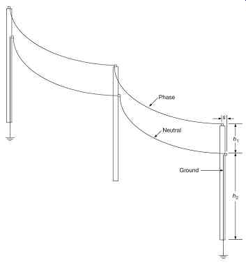
FIG. 1 Portion of single-phase distribution line with multigrounded neutral
(frequency of grounding exaggerated).
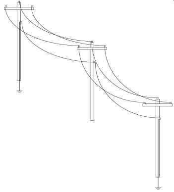
FIG. 2 Portion of three-phase distribution line with multigrounded neutral
(frequency of grounding exaggerated).
This section considers the medium-voltage distribution system. The 120/240 V secondary systems will be examined in the next section.
The three-phase, four-wire multigrounded neutral system can be modeled using the impedance matrix method, where the voltages are measured with reference to ground ( FIG. 3). The load voltage equation is written in the Z-matrix method:
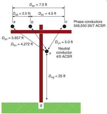
FIG. 3 Line configuration: three-phase multigrounded neutral distribution
line.
...or in expanded form:
eq.2
The impedance terms are calculated from Carson's equations, eliminating the need for a fifth row and column of the matrix for the ground impedances:
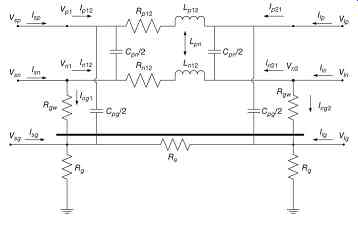
FIG. 4 Simplified equivalent circuit of one segment of a single-phase multigrounded
neutral distribution line.
A person with of resistance will conduct 45.1 mA.
Even if the ground resistance is reduced to zero, and , However, a person will conduct 1 mA or more as long as the grounding resistance is or greater. Another factor that can be used to reduce shock hazard is to reduce the distance between grounds. With grounding, results in 26.9 mA. To achieve 1 mA.
In conclusion, the safe levels of stray current can be determined on the basis of the phase and neutral currents, the grounding resistance, and the spacing of grounds on the poles.
If the neutral is ungrounded, the unbalanced phase current will result in a hazardous voltage on the neutral conductor. Assuming the grounding resistance is now , results in 102.7 V and results in 27.1 V.
To achieve 1.0 V.
3. Secondary Systems: 120/240V Single Phase
The majority of domestic services are fed with the familiar center-tapped 120/240 V single-phase transformer (Kersting, 2009; Mitolo, Liu, and Qiu, 2013). Electrical safety in the home revolves around two major issues, electrical shock from contact with energized conductors and electrical fires due to short circuits (Mitolo, 2009b). Here, we will examine the electrical shock hazards. The voltage from a conductor, whether it is hot or neutral to ground, will produce a current flow through the human body, which can then cause the sensation of shock, injury, or death. In order to minimize hazards in the home, limitations are placed on voltage magnitude, current magnitude, and duration of exposure. The voltage magnitude is limited by means of grounding, the current magnitude by the series impedance of the system and the human body resistance, and the duration by the time to trip of the protective device, normally a ground fault circuit interrupter (GFCI). By means of circuit analysis, we can determine the voltage and current magnitudes, and thus the extent of the risks involved.
The simplified equivalent circuit, FIG. 5, consists of the following elements:
1. Utility system single-phase Thèvenin equivalent source.
2. Utility grounding conductor and ground rod, modeled as a resistance.
3. Utility transformer: single-phase 120/240 V secondary.
4. Service entrance conductors, triplex cable with bare neutral and insulated phase conductors.
These are relatively heavy cables, the neutral often being used for structural support. They are modeled as series and mutual inductances and resistances.
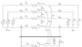
FIG. 5 Equivalent circuit of one segment of a three-phase multigrounded neutral
distribution line, showing mutual impedances.
1. Service entrance, location of revenue metering equipment and service entrance panel.
2. Premises ground, connected to service entrance panel, modeled as a resistance.
3. Premises wiring, consisting of insulated phase and neutral conductors and uninsulated grounding conductor (not shown). These are small-gauge conductors, and may be modeled as resistances.
4. Loads, which may be 120 or 240 V.
The detailed transformer model is shown in FIG. 6.
The transformer is characterized by the following data:
1. Transformer volt-ampere rating, S in kVA
2. Primary voltage,
3. Secondary voltage, ,
4. Transformation ratio:
5. Impedance as a percentage on the kVA base.
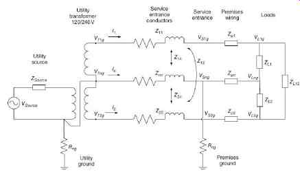
FIG. 6 Equivalent circuit of domestic service with premises wiring and load.
The transformer impedance is divided into three impedances, , , and :
eq.13
The transformer impedance must be converted from percentage to ohms, using the per-unit system:
Determine the primary and secondary full load currents: , .
Calculate the base impedances for the primary and secondary: , .
Convert percentage impedance to ohms:
Convert primary ohms to secondary base:
The service entrance cable is modeled as in equations (3) and (4):
eq.14
eq.15
The loads are modeled as constant impedance to simplify the analysis. The source impedance is assumed to be much less than the transformer impedance and is neglected. The premises wiring impedance is assumed to be much less than the load impedance and is neglected. The final equivalent circuit is shown in FIG. 7.
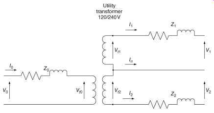
FIG. 7 Detailed model of distribution transformer.
3.1 Example of Stray Currents-Touching a Grounded Conductor
Calculate the current through a person touching a grounded object.
3.2 Example of Stray Currents-With One Conductor Shorted to Neutral
Calculate the current through a person touching a grounded object when Load 1 is shorted phase to neutral. For this example, by varying , , , and a human sees 61.4 mA, , , and a human sees 61.8 mA, , , and a human sees 63.5 mA, showing that for this fault condition, the shock is above the 30 mA threshold for paralysis, and approaches the 75 mA threshold for fibrillation.
4. Remediation of Stray-Current Problems
The shock hazard is caused by the ground loop between the ground at the pole and the ground at the service entrance. By touching the grounded neutral, a person places themselves in parallel with the grounding resistance through which current may be flowing, and a voltage drop present. This results in stray current flowing through the human body.
Removing the ground loop can be done by two methods:
1. Removing the ground at the secondary of the utility transformer, by removing the bond between the secondary neutral and primary ground. The equivalent circuit is shown in FIG. 8. The simplified equivalent circuit used in the calculations above is modified as shown in FIG. 9. In either example considered, the unbalanced circuit or the line to neutral fault, no current will flow from neutral to ground, and no stray current would flow through a human touching the neutral.
2. Removing the premises ground and leaving all grounding in the utility system. The equivalent circuit is shown in FIG. 10.
The simplified equivalent circuit used in the calculations above is modified as shown in FIG. 11. In either example considered, the unbalanced circuit or the line to neutral fault, no current will flow from neutral to ground, and no stray current would flow through a human touching the neutral.
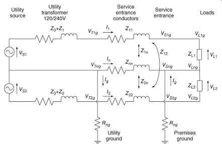
FIG. 8 Equivalent circuit of 120 V system with ground removed from the secondary
of the utility transformer for analysis.
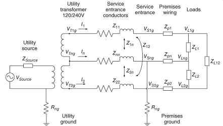
FIG. 9 Equivalent circuit of modified domestic service with ground removed
from the secondary of the utility transformer .
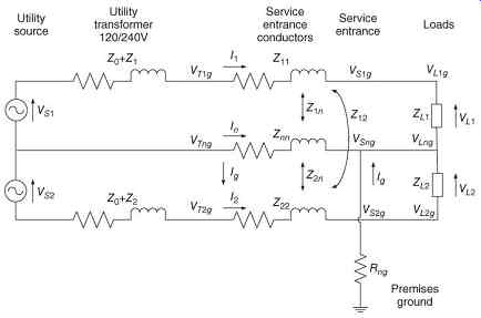
FIG. 10 Equivalent circuit of modified 120 V system with ground removed from
secondary of transformer for analysis .
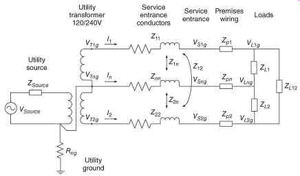
FIG. 11 Equivalent circuit of modified domestic service with ground removed
from secondary of transformer.
The first method is preferable because it requires making the fewest changes to the system, and retains the premises ground, which is considered to provide an extra margin of safety, and cannot be removed easily in existing systems. The household wiring system becomes similar to an industrial power system, with a separately derived ground at the secondary of the distribution transformer. The grounding system is constructed in two isolated zones, one for the medium-voltage distribution and one for the low-voltage distribution. This prevents, for example, current from a medium-voltage ground fault flowing into a low-voltage system.
It prevents a ground fault in the low-voltage system from tripping medium-voltage protection systems, improving protective device coordination ( FIG. 12).
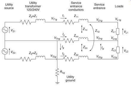
FIG. 12 Equivalent circuit of modified 120 V system with ground removed from
secondary of transformer for analysis.
In some cases, coupling devices have been used in place of the neutral-ground bond at the transformer, which only allow high fault currents to pass, but block low currents due to unbalances. This method keeps the system unsafe when faults occur, and is not recommended.
These methods do not eliminate the ground loops inherent in the multigrounded utility distribution system. However, they do make the system much safer in the user's premises by eliminating the most important ground loop, which has the greatest impact on the people using electric power. What is important regarding the multigrounded system involving grounding the neutral on utility poles is to avoid making contact with the vertical ground wires on the poles. The best practice in this area is to insulate the ground wire, preventing human contact with the conductor.
5. Grounding and Overvoltages in Distribution Systems
Distribution primary circuits typically have one of the following wire configurations:
• Three-wire ungrounded.
• Three-wire uni-grounded.
• Four-wire uni-grounded neutral system.
• Four-wire multigrounded neutral system.
The ungrounded circuit historically has been selected for those systems where service continuity is of primary concern. One of the issues with an ungrounded system is transient overvoltages due to restriking or intermittent ground faults. These type of faults can and do develop substantial overvoltages on ungrounded electrical systems with respect to ground. There have been many documented cases of measured line-to-ground voltages of 3 per unit or higher resulting in equipment damage. In all instances, the cause has been traced to a low-level intermittent arcing ground fault on an ungrounded system. One possible solution is to convert the ungrounded system to a high-resistance grounded system by deriving a neutral point through grounding transformers.
An ungrounded feeder in a power system might look like FIG. 13. The source would be a distribution substation transformer with an ungrounded delta or wye secondary.
Three-phase loads would also be ungrounded delta or wye connected. Single-phase loads would be connected phase to phase. The transformers and feeder conductors will contain distributed capacitances, which form the unintentional grounding system ( FIG. 14). In the transformer, these are mostly from windings to the grounded core. In cables, these are mostly from phase conductors to grounded shields. In overhead lines, these are both phase to phase and phase to ground.
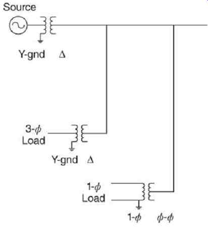
FIG. 13 Ungrounded three-phase feeder.
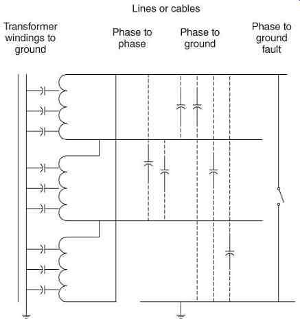
FIG. 14 Distributed capacitances in ungrounded three-phase feeder.
The sequence network derived from this feeder configuration results in the distributed capacitances being shunted across the positive-, negative-, and zero-sequence networks, as shown in FIG. 15. The capacitances have little effect on the positive- and negative-sequence networks, as they are shunted by the source and transformer inductance. However, capacitance is the dominant component of the zero-sequence network, as the zero-sequence capacitive reactance is usually much larger than the conductor impedance.
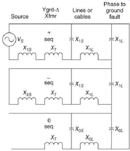
FIG. 15 Interconnected sequence networks of ungrounded feeder.
When a phase-A-to-ground fault occurs as shown in FIG. 14, this results in a series interconnection of the sequence networks. The network of FIG. 15 reduces to the source voltage across the zero-sequence capacitance in FIG. 16. By the use of symmetrical component analysis, the fault current in phase A can be shown to be:
eq.16
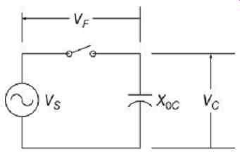
FIG. 16 Simplified sequence network for phase-to-ground fault.
Similarly, the voltages in the unfaulted phases are
eq.17
eq.18
Thus, the voltage from the faulted phase A to ground will be zero, while the other two phases will have their voltage to ground increased by . This is the magnitude of overvoltages that were reported in the 4.8 kV systems. In order to prevent failures due to overvoltages, all equipment in ungrounded systems should be rated for full line-to-line voltage, and not line-to-neutral.
In ungrounded systems where there is very little damping from phase to ground connected relaying, metering, or fault detectors, multiple re-strikes from arcing ground faults can lead to voltage buildups to several times peak line to neutral voltage. An example of the type of overvoltages that can occur is shown in the simulation results of FIG. 17. Here, the arcing fault clears itself at the current zero which occurs during the first voltage peak in the graph. System capacitance holds the voltage across the gap to peak phase to ground voltage.
The arc re-strikes half a cycle later during the next voltage peak. This adds two times peak voltage to the capacitor. A second restrike half a cycle later repeats the cycle, resulting in five times the peak voltage. By this time, insulation failure is likely to result in a permanent fault.
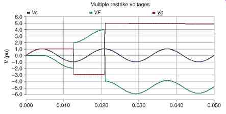
FIG. 17 Simulation of overvoltages due to multiple restrike. Breaker opens
and arc extinguishes at 0.25 cycles, re-strikes occur at 0.75 cycles and again
at 1.25 cycles, resulting in overvoltages of 3 and 5 per unit.
The presence of a resistance in parallel with the distributed capacitance to ground will reduce these overvoltages. The ground detection units, which consist of meters and zero-sequence overvoltage relays, provide such a resistance fed from grounded-wye delta banks of voltage transformers. Additionally, the voltage transformers supply the polarization selector for the ground directional relays on the feeders.
Transient overvoltages caused by multiple re-strikes can be mitigated by rapid detection and clearing of ground faults, the use of higher insulation levels, or by converting to a grounded system.
Ferroresonance is a phenomenon where the nonlinear magnetizing reactance of a (usually) ungrounded and unloaded or lightly loaded transformer resonates with the distributed capacitances in lines or cables feeding the transformer. The resulting voltage oscillation is a distorted, often chaotic, waveform, with peaks as high as five per unit. This will most likely occur during single-phase switching of transformers in systems with high distributed phase to ground capacitances. Ferroresonance can occur in power systems with either grounded or ungrounded sources. However, the primary of the transformer that is involved in ferroresonance is usually ungrounded.
Ferroresonance results in distinctive oscillations that can be detected and recorded by a transient recorder or power quality monitoring system. Monitoring systems may be put in place to verify whether ferroresonance is occurring. These should include oscillographic recordings of voltage transients and the timing of switching events.
6. High-Resistance Grounding of Distribution Systems
The high-resistance grounding bank consists of three single-phase transformers, such as distribution transformers, with a wye-grounded primary and broken delta secondary across which a resistor is placed ( FIG. 18). The function of the grounding bank is to add a resistance across the distributed zero-sequence capacitance ( FIG. 19). The value of the grounding resistance is usually made equal to the system charging reactance. This will result in a single phase to ground fault current of 1.4 times the system charging current. Typical fault currents in high-resistance grounded systems are in the range 1-10 A.
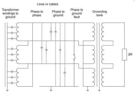
FIG. 18 High-resistance wye-broken delta grounding bank added to the system
of FIG. 13.
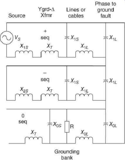
FIG. 19 Interconnected sequence networks with high-resistance grounding bank.
The grounding resistor will limit system overvoltages due to multiple restrike. For example, Figure eq.20 shows the restrike simulation of the previous example with high-resistance grounding equal to the system capacitive reactance. The rationale for choosing the resistance to equal the charging capacitance is shown in Figures 9.21 and 9.22. These are plotted for a 5.04 kV (2.9 kV phase to ground) system with 3.48 mF charging capacitance and... Lowering the resistance below this value will result in a rapid increase in fault current from 5 to 10 A, while doubling it will increase the transient overvoltages from 2 to 2.5 per unit.
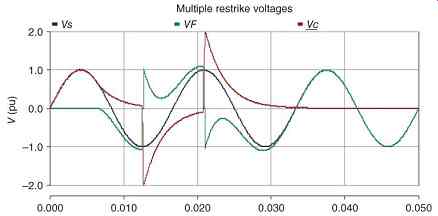
FIG. 20 Restrike overvoltages of FIG. 17 limited by high-resistance grounding
with R = XC to less than 2.5 per unit.
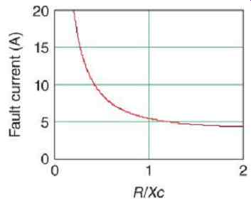
FIG. 21 Fault current versus resistance in a typical high-resistance grounded
system.
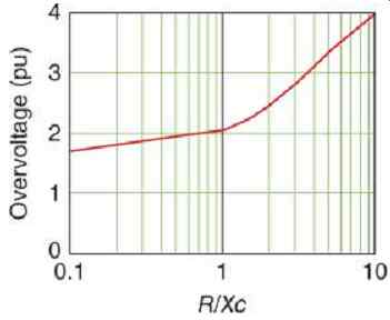
FIG. 22 Overvoltage due to restrike versus resistance in a typical high-resistance
grounded system.
The grounding resistor will not limit overvoltages due to single-line-to-ground faults.
The equipment insulation level must continue to be line to line as in ungrounded systems.
The grounding resistor will limit system overvoltages due to ferroresonance as long as the grounding resistance is less than or equal to XC (Mason, 1956, p. 209). In sizing high-resistance grounding systems, resistances in the range 0.5-1.0 times the system charging reactance are acceptable.
6.1 Methods of Determining Charging Current
It is recommended that charging current measurements be performed on one or more banks in order to verify calculated results. The charging current is normally calculated by summing the capacitances to ground of all connected equipment, such as
• Cables
• Overhead lines
• Power transformers
• Instrument transformers (voltage)
• Motors
• Generators
• Surge capacitors
Any power factor correction capacitors should be connected phase to phase and not phase to ground. Since cables are usually the largest contributors to the total capacitance, the total length of cables and the capacitance to ground per phase per unit length are the key pieces of data required.
In low-voltage systems, measurement of ground fault current on an intentionally grounded phase is feasible (IPC, undated). This method has also been used on medium-voltage systems, but lack of a solid ground to measure to may cause inaccuracy in the results. If a zero-sequence window Current Transformer (CT) is installed on a circuit, charging current can be measured directly.
Charging current can be measured during grounding bank installation.
When the grounding bank is being installed, connect the three secondary windings in delta, without the resistor ( FIG. 23) and measure the delta current. In the absence of a fault, this should be close to zero. Apply three times rated secondary voltage to the broken delta and measure the current. The charging current will be the measured delta current divided by the ratio of the distribution transformer, DTR:
eq.19
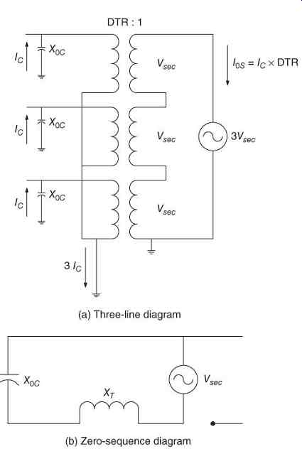
FIG. 23 Measurement of charging current using voltage source and grounding
bank. (a) Three-line diagram and (b) zero-sequence diagram.
With a resistor in the broken delta ( FIG. 24), the resistance and capacitance are in parallel across the voltage source. The magnitude of the measured current is increased due to the added resistance:
eq.20
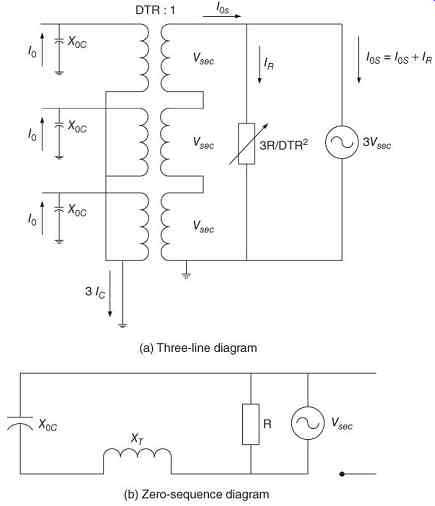
FIG. 24 Field tuning of grounding resistor. (a) Three-line diagram and (b)
zero-sequence diagram.
Break the delta and install the resistor. Adjust the taps on the resistor until the current is at its closest to 1.414 times the current previously measured. Remove the voltage source.
The application of high-resistance grounding banks to ungrounded three-phase distribution systems has been shown to be useful in decreasing transient overvoltages due to multiple restrikes and ferroresonance.
Simulation and research results show that a resistance in the range 0.5-1.0 times the zero sequence capacitive reactance will be most effective in reducing these overvoltages.
It is difficult to measure zero-sequence charging currents in an ungrounded system due to the lack of a ground to measure against. A new method was proposed for measuring charging currents and tuning high-resistance grounding banks. This method only requires the use of an AC voltage source and an ammeter.