AMAZON multi-meters discounts AMAZON oscilloscope discounts
1. Introduction
In areas where explosive mixtures of gas and air can be present, sparks given off by electrical equipment or hot surfaces on this equipment constitute a potential hazard, and the consequences of an explosion can be disastrous.
Combustible materials can form explosive atmospheres and can under certain circumstances cause an explosion. Such materials are used widely in the chemical, mining and other industries and even in everyday life. The concept of 'explosion protection' of electrical equipment has been developed and formalized in order to prevent explosive accidents in hazardous areas during the normal operation of the equipment.
The coal mining industry has provided one of the main pressures for the development of special equipment, procedures, standards and codes because of its especially hazardous working environments. Davy's safety lamp for miners is an example of a piece of equipment developed specifically for use in hazardous areas. The legacy of the importance of this industry remains today through the difference in the regulations which apply to mining and to other hazardous areas. Apart from mining, hazardous areas are found especially in offshore gas and oil installations and in petrochemical complexes.
There are numerous standards and codes of practice governing the manufacture, selection, installation and maintenance of electrical equipment in potentially hazardous areas. These tend to differ around the world and despite harmonization across the European Union, the complexity can be intimidating. A summary is presented in section 6. Because of the special implications for safety, equipment and systems for use in hazardous areas must be tested and certified by approved authorities; certification is covered in section 5.
2. Hazardous areas
Hazardous areas are classified into zones according to the nature of the gases present in the potentially explosive atmosphere, and the likelihood of that atmosphere being present. The nature of the atmosphere is characterized by the chemical composition of the gas and its ignition temperature, and the notions of gas grouping and temperature classification have been developed in order to formalize this.
A useful concept in the consideration of how explosions occur is the hazard triangle shown in Fig. 1. The sides of the triangle represent fuel, oxygen and a source of ignition, all of which are required in order to create an explosion. For the purposes of this Section, a fuel is considered as a flammable gas, vapor or liquid, although dust may also be a potential fuel. Oxygen is of course present in air at a concentration of about 21 percent. The ignition source could be a spark or a high temperature. Given that a hazardous area may contain fuel and oxygen, the basis for preventing explosion is to ensure that any ignition source is either eliminated or prevented from coming into contact with the fuel-oxygen mixture.
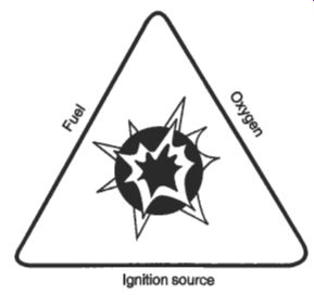
Fig. 1 The 'hazard triangle'
2.1 Zone classification
The zone classification defined in IEC 79 is used in Europe and most other parts of the world; it is summarized in Table 1. Various types of explosion protection are available, and their suitability for the different zones is shown in the table.
Table 1 IEC 79 classification of hazardous area zones
In the USA hazardous areas are classified in a slightly different way, according to the National Electrical Code. In brief, hazardous areas are classified either as Division I! where ignitable concentrations of flammable gases or vapors may be present during normal operation, or as Division 2, where flammable gases or vapors occur in ignitable concentrations only in the event of an accident or a failure of a ventilation system.
2.2 Gas grouping and temperature classification
The energy required for ignition differs from gas to gas, and the grouping of gases together with their classification by temperature is used in Europe to describe the suitability of a piece of electrical equipment for use with explosive atmospheres of particular gases.
Table 2 lists common industrial gases within their appropriate groups. Gas group I is reserved for the classification of equipment suitable for use in coal mines.
Gas group I1 contains those gases found in other industrial applications, and it is subdivided according to the relative flammability of the most explosive mixture of the gas with air.

Table 2 CENELEC/IEC gas grouping
Table 3 CENELECDEC temperature classification
Temperatures are classified from T1 to T6, as shown in Table 3. The levels show the maximum surface temperature permitted for an equipment which has been assigned that temperature class, and the common gases for which each class is appropriate are also shown.
North American practice is to define hazardous materials in classes. Flammable gases and vapors are Class 1 materials, combustible dusts are Class 2 materials and 'flyings', such as sawdust, are Class 3 materials. Class 1 is subdivided into four groups depending on their flammability: A (including acetylene), B (including hydrogen), C (including ethylene) and D (including propane and methane). The subgroup letters are in the opposite order of flammability to the IEC groupings shown in Table 2. The North American temperature classification is similar to the IEC system shown in Table 3, but the classes are further subdivided to give more specific temperature data.
2.3 Area assessment procedure
Companies using flammable materials carry out an area assessment exercise in accordance with national standards such as BS 5345, Pt 2 in the UK or relevant industry codes such as those existing in the petroleum and chemical industries. In general, this assessment procedure results in a written report which identifies and lists the flammable materials used, records all the potential hazards with their source and type, identifies the extent of the zone taking into account for instance the type of potential release of flammable material and ventilation systems, and includes other relevant data. This procedure is complicated, and there are specialist companies which offer a commercial hazardous area assessment service.
3. Protection concepts for electrical equipment
There is a need for electrical power in hazardous areas to supply motors, lighting, control equipment and instrumentation, and a range of equipment is available which has been tested and certified to the appropriate standards. Equipment that has been designed and tested in Europe usually carries a string of codes which gives information about its suitability for use, and also carries the mark of the certifying body.
The definitions of gas group and temperature classification have already been explained. The following sections describe the basis of the protection code.
According to the harmonized European standard EN 50014, electrical equipment for use in explosive atmospheres can be designed with various protection concepts; these are listed in Table 4. Also listed in the table are the Ex 'N' and Ex 's' concepts which have not been the subject of European harmonization. They are not covered in EN 50014 and do not attract the EEx mark signifying certification to a harmonized European standard.
Table 4 Types of protection
The engineer designing an electrical system has to make a choice regarding the method of protection to be used, and has to select apparatus and components accordingly.
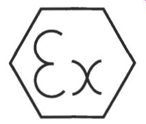
Fig. 2 The EN conformity mark for certified explosion-protected equipment
In practice, the majority of electrical equipment for use in hazardous areas will be designated according to the EEx 'd', EEx 'e', Ex 'N/'n' or EEx 'i' concepts and these four are therefore highlighted in the following sections.
3.1 Flameproof enclosure - EEx 'd'
In this concept, those parts of the electrical equipment that can ignite an explosive air-gas mixture are contained in an enclosure. The enclosure can withstand the pressure created in the event of ignition of explosive gases inside it, and can prevent the communication of the explosion to the atmosphere surrounding the enclosure.
The rationale is the containment of any explosion which may be created by the equipment. The concept is therefore applicable to virtually all types of electrical apparatus, provided that the potential sparking or hot elements can be contained in a suitably sized and sufficiently strong enclosure.
The factors taken into account by equipment manufacturers and system designers include:
arc and flame path lengths and types
surface temperature
internal temperature with regard to temperature classification
distance between components in the enclosure and the enclosure wall (12 mm minimum is specified by the standard)
Some types of component are unsuitable for use in a flameproof enclosure. These include rewireable fuses and components containing flammable liquids.
A major consideration in the use of EEx 'd' enclosures is the making of flameproof joints, which must be flanged, spigoted or screwed. The maximum gaps and minimum lengths of any possible flame path through ajoint are defined by the standard, which also lays down requirements for the pitch, quality and length of screw threads. The nature of the construction required is shown in Fig. 3 which illustrates an EEx 'd' induction motor.
The certification for EEx 'd' equipment involves examination of the mechanical strength of the enclosure, and explosion and ignition tests under controlled conditions.
3.2 Increased safety - EEx 'e'
Measures are taken in this concept to prevent sparks or hazardous temperatures in internal or external parts of the electrical equipment during normal operation. The guiding philosophy here is the prevention of explosion from normally non-sparking/ arcing or hot equipment.
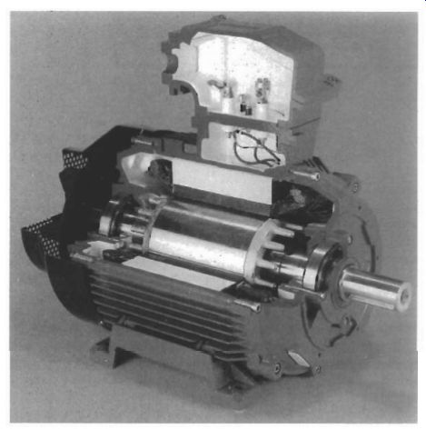
Fig. 3 Sectional illustration of an EEx 'd' induction motor.
No sparking devices can be used, and various electrical, mechanical and thermal methods are used to increase the level of safety to meet the certification test requirements.
One advantage of increased safety protection compared with flameproof protection is that boxes and enclosures can be made of plastics and other materials that are easier to work with. Examples of equipment commonly designed and constructed to EEx 'e' protection include luminaires, terminal boxes and motors. Examples of an EEx 'e' junction box, emergency luminaire and cable gland are shown in Figs 4, 5 and 6 respectively.
Key design considerations for EEx 'e' equipment are the electrical, physical and thermal stability of the materials and the compatibility of different materials which might be used for items such as terminations. Specialist manufacturers have been ingenious in the design of electrical terminations for EEx 'e' equipment to ensure firm, positive and maintenance-free connection of conductors.
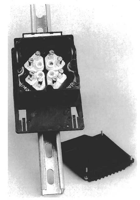
Fig. 4 EEx 'e' junction box and mounting plate
3.3 Non-sparking - Ex 'n'
This is a British designation for electrical equipment, commonly known as 'Type N', which is suitable for use in Zone 2 applications, but not in Zone 1. It is not yet incorporated into harmonized European standards and does not therefore carry the EEx designation.
The concept combines certain aspects of EEx 'e' and EEx 'i' protection in its use of 'non-incendive' circuit elements and in the design for increased safety. Equipment manufactured with Type N protection includes terminal boxes, luminaires and motors.
Because of the less hazardous nature of locations assessed as Zone 2 and the consequently less demanding requirements of the standard, this equipment can be manufactured more simply and at less cost than other types of explosion-protected equipment for Zone 1 use.

Fig. 5 EEx'e' Zone 1 emergency luminaire

Fig. 6 Deluge-protected cable gland with integral entry thread '0' ring
seal.
3.4 Intrinsically safe - Ex 'i'
In an Intrinsically Safe (IS) equipment, under normal operation and certain specified fault conditions, no sparks or thermal effects are produced which can cause ignition of a specified gas atmosphere. Sparks or thermal effects are not produced because the energy in the IS circuits is very low. IS circuits are control and instrumentation circuits rather than power circuits.
According to the Code of Practice in BS 5345, Pt 4, in order to be defined as a 'simple apparatus' the maximum stipulated voltage that a field device can generate is 1.2 V, with current, energy and power not exceeding 0.1 A, 20 mJ and 25 mW respectively. IS circuitry exceeding these ratings may still meet the requirements of EEx 'i', but it requires certification.
There are two types of EEx *i' protection, these being EEx 'ia' and EEx 'ib'. EEx 'ia' equipment will not cause ignition in normal operation, with a single fault and with any two faults. A safety factor of 1.5 applies in normal operation and with one fault, and a safety factor of 1.0 applies with two faults. EEx 'ia' equipment is suitable for use in all zones, including Zone 0. An example of EEx 'ia' equipment is the pressure transmitter shown in Fig. 7.
EEx 'ib' equipment is incapable of causing ignition in normal operation and with a single fault. A safety factor of 1.5 applies in normal operation and with one fault.
A safety factor of 1.0 applies with one fault if the apparatus contains no unprotected switch contacts in parts which are likely to be exposed to the potentially explosive atmosphere. and the fault is self-revealing. EEx 'ib' equipment is suitable for use in all zones except Zone 0. Components for IS circuits contain barriers to prevent excessive electrical energy from entering the circuit. The two principal types are Zener barriers, which are used when an IS earth is available, and galvanically isolated barriers, which are used when an IS earth is not available. An IS earth must be provided by a clearly marked conductor of not less than 4 mm* cross-section and with an impedance no greater than 1 R from the barrier earth to the earth on the main power supply.
Energy can be stored in the inductance and capacitance of a cable, and this must be taken into account when designing an IS circuit. This is achieved by strict control of capacitance and LIR ratios in conjunction with Zener barriers or galvanic isolators.
BS 5308 covers polyethylene-insulated cables for use in petroleum refineries and related applications and the PVC-insulated cables which are widely used in chemical and industrial applications, and cables meeting this specification may be suitable for Group 11 IS systems.
3.5 Pressurized - EEx 'p'
This type of protection uses air or inert gas to maintain a positive pressure within the enclosure or room. The positive pressure prevents the entry of flammable gas or vapor into the protected area.
An alternative method is to reduce the volume of gas or vapor within the enclosure or room below the explosive level of the gas-air mixture by dilution from a clean external source. The main features of a pressurization installation are shown in Fig. 8, and Fig. 9 shows the layout of a leakage compensation unit.
3.6 Oil immersion - EEx '0'
This rarely encountered protection refers to apparatus in which the ignition of a gas- air mixture is prevented by immersing the live or sparking equipment in a specified minimum depth of oil. The necessary depth is determined by testing.

Fig. 7 EEx 'ia' field-cased pressure transmitter.
3.7 Quartz-sand filled - EEx 'q'
EEx 'q' protected apparatus has the live or sparking elements immersed in granular quartz or other similar material.
3.8 Encapsulation - EEx 'm'.
In this form of protection, potential sources of ignition are encapsulated to prevent them from coming into contact with explosive atmospheres.
3.9 Special protection - Ex 's'.
Ex 's' equipment has been shown by test to be suitable for use in the appropriate zone, although the apparatus does not comply with the standard of any of the established concepts previously described.
----------

Fig. 8 Main features of a pressurization installation
----------

Fig. 9 Internal view of a leakage compensation unit
4. Installation, inspection and maintenance
In addition to giving information on the selection of electrical equipment for use in hazardous areas, BS 5345 also contains guidance on the installation, inspection and maintenance of equipment. The code is divided into nine parts. Part 1 gives general guidance and part 2 covers the classification of hazardous areas. Each of the remaining parts is specific to one of the types of protection concept. It contains useful general information concerning electrical work in hazardous areas, but it does not cover work in mines or areas where explosive dusts may be present, and it is not intended to replace recommendations which have been produced for specific industries or particular applications.
In general, operation and maintenance should be taken into account when designing process equipment and systems in order that the release of flammable gases is minimized.
For example, the requirement for routine opening and closing of parts of a system should be borne in mind at the design stage.
No modifications should be made to plant without reference to those responsible for the classification of hazardous areas, who should be knowledgeable in such matters. Whenever equipment is reassembled, it should be carefully examined. The code gives recommended inspection schedules for equipment of each type of protection concept. These schedules set out what should be inspected on commissioning and at periodic intervals. For all equipment, the protection type, surface temperature class and gas group should be checked to ensure that the equipment is suitable for its zone of use, and circuit identification should also be checked.
Some of the areas of recommendation of the code are presented below, in particular from those parts relating to EEx 'd', EEx 'e' and EEx 'i' equipment, but these highlights can in no way replace the code itself. The electrical engineer requiring detailed and specific guidance on the installation, inspection and maintenance of electrical equipment in hazardous areas should consult BS 5345 or other codes relevant to specific industries or applications.
4.1 Flameproof EEx 'd' equipment
For installations making use of flameproof enclosures, the code recommends ensuring that solid obstacles such as steelwork, walls or other electrical equipment cannot be close to flanged joints or openings. Minimum clearance distances of up to 40 mm are given.
Gaps should be protected against the ingress of moisture with approved non- setting agents, and extreme care should be taken in the selection of these agents to avoid the potential separation of joint surfaces.
The code specifies the type of threads to be used for entry tappings into flameproof enclosures, and it is stressed that directions contained in the certification documents for cable systems and terminations should be followed. The types of cables suitable for use and their appropriate methods of entry are also specified. EEx 'd' equipment with integral cables where the cable terminations are encapsulated must be returned to the manufacturer if maintenance is required.
4.2 Increased safety EEx 'e' equipment
The section of the code dealing with EEx 'e' equipment includes a recommendation that the ratings of lamps are correct, since these may have been replaced. An appendix gives guidance on the chemical influence of combustible gases on certain mechanical and electrical properties of any insulating materials such as panels, gaskets or encapsulation.
An appendix covering cage induction motors and their associated protection equipment gives recommendations which are intended to ensure that all parts of the motor do not rise above a safe temperature.
4.3 Intrinsically safe EEx 'i' equipment
The part of the code dealing with EEx 'i' equipment pays particular attention to the interconnecting cables used in IS systems. It recommends, for instance:
insulation thicknesses
minimum conductor sizes to ensure temperature compliance in fault conditions
specific separations between individual IS circuits and earth
screening and mechanical properties of cables
The use of multicore cable is considered, as is the siting of cables to avoid potential induction problems. In general, cable entries should be designed to minimize mechanical damage to cables.
With all IS equipment, the need to follow the specific requirements of the certification documents is emphasized and it is recommended that during inspection attention is paid to lamps, fuses, earthing and screens, barriers and cabling. Certain specified on- site testing and maintenance of energized IS circuits is permitted inside the hazardous area, provided that the test equipment is certified as intrinsically safe in itself, and that conditions on the certification documents are followed.
5. Certification
The certification process involves an assessment of the equipment with regard to its conformity to the specific standard sought, an examination of a prototype to ensure that it complies with the design documents, and testing. The certified design is defined in a set of approved drawings listed in the certificate.
Within Europe there are national authorities or test houses which issue certification documents for electrical equipment in order to prove that the equipment meets a specific standard for explosion protection. Table 5 lists these authorities by country.
In the UK BASEEFA and SlRA are the accredited authorities. As well as being accepted throughout the European Union, certification by BASEEFA and SIRA is also recognized in other parts of the world, especially the Middle East and Far East.
Table 5 Certifying authorities
Certification to the relevant standard for use in mines is carried out in the UK by MECS. The procedure is similar to the certification to standards for other hazardous areas, but in addition to explosion protection requirements, electrical equipment must also provide the high degree of electrical, mechanical and operational safety (pit-worthiness requirements) demanded by the Mines Inspectorate.
Once a product has been tested and certified to a specific standard by an authorized test house, the equipment manufacturer may then certify that product under license from the test authority. Equipment certified as meeting the European Norms carries the distinctive hexagonal conformity mark shown in Fig. 2. Individual components usually have conditions for safe use attached to their certificate. A 'certificate of conformity' for a complete piece of electrical apparatus allows installation in hazardous areas without further verification.
5.1 ATEX Directive
The current procedure for manufacturers introducing products to the market has been outlined in the previous section. In future, however, manufacturers will follow Directive 94/9/EC, dated 23.3.1994. This came into effect on 1.3.1996, and will become mandatory from 1.7.2003. This new Directive has a wider scope and differs from the current procedure in the following respects:
CE marking must be applied with explosion-protected marking mining and surface gas groups are addressed electrical and mechanical equipment is covered equipment categories (1-3) are included the issue of dust is addressed The Directive places more emphasis on continued compliance and does not allow for different interpretations.
Installers and operators will not see a great change in equipment, as most electrical equipment currently on the market will comply with the new Directive. They will see different equipment markings, with more information being included on equipment labels.
Table 6 International, regional and national standards relating to electrical equipment for hazardous areas
6. Standards and codes of practice
As in many areas of industry, European Norms (EN) exist alongside equivalent British Standards. The ENS, with equivalent BS and IEC references are shown for the different explosion protection concepts in Table 6. The origins of the ENS are in the European Directives published in 1975 and 1979 concerning electrical equipment for use in potentially explosive atmospheres. A separate Directive relating to mines was published in 1982.
It is important for the electrical engineer to be aware of the ENS and their equivalents in their latest editions because they determine the types of equipment available for use, and also impinge on installation procedure.
References
There are a few reference texts on this subject and the reader is referred for further detail to the comprehensive literature which is produced by reputable manufacturers. This is produced in much greater depth than ordinary commercial literature because of the complexity of specifying, installing and using equipment for hazardous areas.