The cylinder head acts as the backing plate for the head gasket and must, above all, be rigid. Iron is the preferred material, although automotive and other light duty engines often are fitted with aluminum heads. Because of its good conductivity, aluminum assists cooling and eliminates the steep thermal gradients that iron is heir to. In other words, aluminum heads are less likely to develop local hot spots.
But, in common with most other structural materials, the weight savings of aluminum come at the cost of rigidity. Aluminum has a third the density of iron and a third the rigidity. To achieve the same level of stiffness, an aluminum head would have to weigh as much as the iron head it replaces. Good design practice and closely spaced head bolts ameliorate the problem, but aluminum heads are always less rigid than their cast-iron equivalents.
And while aluminum can be heat-treated to T6 or T7 hardness, few manufacturers bother, since the benefits of heat treating disappear at high temperatures. The light-metal alloys in general use exhibit a rapid loss of strength at temperatures above 200 degr. C (392 degr. F). Overheating an engine is almost guaranteed to warp the head.
To further complicate matters, cast-iron has a lower rate of thermal expansion than aluminum. When bolted to an iron block, an aluminum head tends to bow upward, reducing the clamping force on the gasket. This phenomenon is discussed in the section that deals with head straightening.
The cylinder head forms an important part of the cooling system. The water jacket should be cast with large passages that resist clogging. Some designs employ diverters, or baffles, to direct the coolant stream to valve seats and other critical areas. Standard practice is to integrate block and head cooling, but several industrial engines separate the two so that a blown head gasket does not contaminate the crankcase oil with antifreeze.
Fasteners-capscrews or studs-should be arranged symmetrically insofar as rocker pedestals, valve ports, and injector and glow-plug bosses permit.
Combustion chamber types
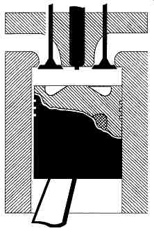
FIG. 1 DI or open chamber.
A vast amount of development work was done in the 1920s and 30s on optimum combustion chamber shapes. The effort continues-with emphasis on control of emissions-but the main outlines of the problem and the alternatives appear to be firmly established.
The central problem is to provide a mechanism for mixing fuel with the air. The fuel spray must be dispersed throughout the cylinder so that all available oxygen takes part in the combustion process. As fuel droplets move away from the nozzle, the chances of complete combustion are progressively lessened. There is less oxygen available because some of the fuel has already ignited. In addition, the droplets shrink as they travel and successive layers of light hydrocarbons boil off.
Direct injection
Direct Injection (DI) chambers, also called open or undivided chambers, resemble those used in carbureted engines ( FIG. 1). These symmetrical chambers have small surface areas and, to reduce heat losses further, generally take the form of a cavity in the piston crown.
Until the advent of multiple-orifice, staged injectors and the high-pressure fuel systems necessary to support them, DI chambers compensated for poor fuel penetration by imparting energy to the air charge. Two mechanisms were involved: swirl and squish. The exit angle of the intake-valve seat imparted a spinning motion, or swirl, to incoming air stream. Squish was achieved by making the edges of the piston crown parallel to the chamber roof. As the piston neared top dead center (tdc), air trapped between these two faces "squished" inward, toward the piston cavity.
Mixing was less than perfect, which resulted in ignition delay and rapid rises in cylinder pressure as the accumulated fuel charge exploded. As a result, DI was con fined to stationary, heavy trucks and marine engines where noise, vibration, and exhaust smoke counted for less than fuel economy.
The breakthrough came in the late 1980s in the form of electronic injectors that sequenced fuel delivery to "soften" combustion and reduce ignition delay. Ultrahigh fuel pressures, coupled with orifice diameters as small as 0.12 mm, or twice the thickness of a human hair, atomize the fuel for better mixing. The fuel charge became the primary vehicle for mixing that, in some cases, enabled designers to eliminate the pumping losses associated with generating air turbulence. DI also opened the way for massive power increases. By substituting DI for the Ricardo Comet V cylinder head originally fitted, enlarging the bore, and adding a turbocharger, Volkswagen increased the power output of its four-cylinder engine by a factor of 3.4.
Indirect injection
Indirect injection (IDI) uses energy released by combustion to drive the fuel charge deeply into the air mass. The combustion chamber is divided into two sections with the larger chamber formed by the piston top and cylinder-head roof.
Combustion begins in a smaller chamber, usually located over the piston. A passage, often in the form of a venturi, connects the two chambers.
Fuel mixing, at least with low-pressure injectors, is enhanced since the fuel droplets exit the smaller chamber at very high velocities. Because peak pressures occur in the smaller chamber and don’t act on the piston, IDI reduces noise and combustion roughness. The first diesel passenger cars would not have been commercially accept able without IDI, and many light-duty engines continue to use this technology.
On the debit side, indirect injection imposes pumping losses since the piston must work to pressurize the small antechamber. In addition, this chamber acts as a heat sink, bleeding thermal energy that could be better employed in turning the crankshaft. For cold starting, the air charge must be heated with glow plugs. All of these chambers expel a jet of burning fuel that rebounds off the piston. A supercharger or turbocharger increases the temperature of the air charge and the vulnerability of the piston to meltdown.
Precombustion chamber
The precombustion chamber was first used on the Hornsby-Ackroyd low compression oil engine and subsequently by Caterpillar, Deutz, and Mercedes-Benz, and other diesel manufacturers ( FIG. 2). The precombustion chamber, also known as a hot bulb because of its shape and absence of any provision for cooling, occupies 25-40% of the total swept volume.
As the piston approaches tdc, the injector opens to send a solid stream of fuel into the hot bulb. The charge ignites, bulb pressure rises, and a stream of burning fuel jets through the connecting channel and into the main chamber, where there is sufficient air to complete combustion. The smaller the channel, the greater the acceleration and, all things equal, the more complete the fuel-air mixing. These chambers employ pintle-type injectors.
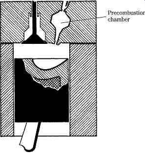
FIG. 2 IDI in the form of a precombustion chamber.
Swirl chamber
The swirl, or turbulence, chamber is similar in appearance to the precombustion chamber, but functions differently ( FIG. 3). During compression, the disc-shaped or spherical antechamber imparts a circular motion to the air, which accelerates as the piston approaches tdc. The injector is timed to open at the peak of vortex speed. As the piston rounds tdc, combustion-induced pressure in the antechamber reverses the flow. A turbulent stream of burning fuel and superheated air exits the antechamber and rebounds off the piston to saturate the main chamber.
The swirl chamber was invented by Sir Harry Ricardo during the late 1920s and underwent numerous alterations during its long career. Except for Mercedes-Benz, most diesel cars and light commercial vehicles of the postwar era and for many years after employed the Ricardo Comet V chamber. These chambers are more economical than hot-bulb chambers, but are noisier.
The 6.25L engine used by General Motors for pickup trucks during the 1980s and early 90s demonstrates the tradeoffs implicit in combustion-chamber design. While the Ricardo chamber depends upon swirl for mixing, velocity is also important. Initially, these GM engines were set up with a small-diameter port between the main and swirl chambers. The pressure drop across the port generated velocity that, in conjunction with swirl, resulted in good air-fuel mixing and fuel economy. Near the end of the production run, GM acquiesced to customer demands for more power by enlarging the connecting port. More fuel could be passed, but thermal efficiency suffered. Fuel economy, which had approached 20 miles/gal, dropped to 14 or 15 mpg.
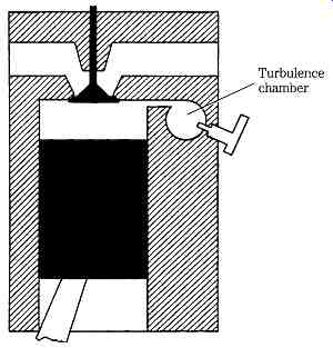
FIG. 3 IDI in the form of a turbulence chamber, the most common of which
were developed by Ricardo Ltd.
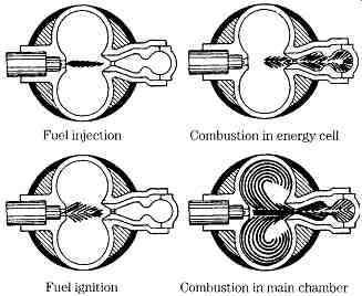
FIG. 4 Hot bulb or Lanova IDI chamber is seen most often on older Cat engines.
Energy cell
Examples of the energy cell, or Lanova divided chamber, can still be encountered in vintage Caterpillar tractor engines (FIG. 4). The cell consists of a kidney shaped main chamber, located over the piston, and a secondary chamber, or energy cell, which is divided into two parts. The cell opens to a narrow throat, situated between the two lobes of the main chamber.
During the compression stroke about 10% of the air volume passes into the energy cell. The injector, mounted on the far side of the main chamber, delivers a solid jet of fuel aimed at the cell. A small percentage of the fuel shears off and remains in the main chamber and some collects in the cell chamber closest to the piston bore. But most of the fuel dead-ends in the outermost cell chamber. . Ignition occurs in this outer chamber. Unburned fuel and hot gases accelerate as they pass through the venturi between the two cell chambers and enter the main chamber. The rounded walls of the main chamber impart a swirl to the charge to promote better mixing.
Valve configuration
Modern engines employ overhead valves (ohv), although side-valve engines still find buyers. Mounting the valves over, rather than alongside, the piston makes for a cleaner, less heat-absorbent combustion chamber and permits larger valve diameters.
Overhead valves are generally driven from a block-mounted camshaft through pushrods and rocker arms ( FIG. 5). High-performance auto engines and commercial engines with unit injectors employ a single overhead camshaft (ohc) that acts on the valves through rockers. At present, diesel engines don’t turn fast enough to justify the reduction in reciprocating weight that double overhead camshafts (dohc) would provide.
For good volumetric efficiency, valves should be as large as possible. Some American trucks and many European passenger cars have four valves per cylinder to improve breathing and power output. With a pent-roof chamber, four valves can provide a flow area of about a third of the area of the piston crown. In contrast, the flow area of two parallel valves is only a fifth of the crown area.
When purchasing aftermarket valves, it’s useful to know that the SAE classifies valve steels into four groups:
• NV low-alloy steels for intake valves,
• HNV high-alloy steels for intake valves,
• EV austenitic steels for exhaust valves; and
• HEV high-strength alloy for exhaust valves.
When upgrading intake valves, one would do well to specify SAE-rated EV8 21-4N austenitic steel that contains 21% chromium and 3.75% nickel, and tolerates temperatures of 1600 degr. F (871 degr. C). Inconel 751, which the SAE classifies as HEV3, is preferred for exhaust valves because of its hot strength. This nickel-based alloy contains 16% chromium and 3% titanium.

FIG. 5 Typical ohv valve train, driven from the camshaft via pushrods and
rocker arms. Marine Engine Div., Chrysler Corp.
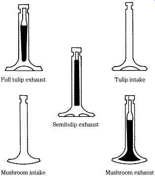
FIG. 6 Tulip and mushroom valves can still be encountered on older engines.
But contemporary practice is to flatten the valve crown to reduce heating.
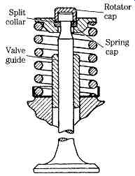
FIG. 7 The GM Bedford valve assembly includes rotator cap (Rotcap), split
collar keepers, spring cap, and spring.
Regardless of the steel used, long-lived exhaust valves use sodium as a medium of heat exchange. When heated, sodium turns liquid and transfers about 40% of the heat load to the valve guide. In contrast, solid-steel valves transfer only 25% of the heat to the guide, the rest of it going through the seat. Because sodium combines explosively with water, these valves should be treated with respect. Any discarded valves should be clearly marked as containing sodium.
Valve inserts, or seats, are an interference fit in the cylinder head. In addition to forming a gas seal with the valve face, the seats provide a major path for heat transfer from the valve face. Consequently, the seats are adjacent to fins on air-cooled engines or surrounded by water on liquid-cooled types. Sintered-iron alloys are often used for intake seats and nickel-steel for the exhausts.
While valves are forced open mechanically by the camshaft, spring pressure seats them. As the springs weaken in service, it’s possible for the valve train to "lead" the cam. The acceleration imposed during lift times the reciprocating weight of the train (cam followers, pushrods, half of the mass of the rocker arms, and valves) over comes spring tension and the valves float open. A similar problem occurs during seating: insufficient spring tension permits valves to bounce several times before coming to rest. These effects become more severe as engine speeds increase.
The angle of the faces varies with many manufacturers using a 30 degr. angle on the intakes and 45 degr. on the exhausts. The steeper angle imposes a flow restriction, but generates the higher seating forces needed for exhaust valves. Valve guide material ranges from chilled iron to manganese or silicon bronze.
Before you begin
Some repairs, such as head-gasket replacement, are normally done on site.
Other operations require the assistance of a machinist. But the mechanic needs to understand enough about the compromises involved in returning worn parts to ser vice to be able to evaluate the machinist's work. And, as far as possible, the mechanic should keep current with the technology, such as diamond-like carbon (DLC), titanium nitride (TnN), and chromium nitride (CrN) anti-friction coatings, and isotropic polishing. The latter involves the use of irregularly shaped ceramic pellets in a vibratory machine. The process, which takes about ten hours to complete, extends valve and valve-train life by removing stress risers and microscopic peaks.
Replacement parts can be purchased from the original equipment manufacturer (OEM) or, for the more popular engines, from the aftermarket. Some aftermarket parts are equal to those supplied to the OEM and may, in fact, be the same parts.
Others are not so good in ways that might not be apparent until the engine runs a few hundred hours.
Counterfeit parts, disguised as OEM parts, are widely marketed and sometimes by authorized factory dealers. Be suspicious of a part that costs considerably less than it should or that differs from the original in finish, code number, or packaging.
Diagnosis
Head-related problems usually involve loss of compression in one or two cylinders, a condition that is signaled by a ragged idle, by increased fuel consumption, and in some instances, by exhaust smoke. An exhaust temperature gauge, with switch-controlled thermocouples on each header, will give early warning. Exhaust from weak cylinders will be cooler than the norm. You can cross-check by disabling one injector at a time while the engine ticks over at idle. A cylinder that causes less of an rpm drop than the others does not carry its share of the load. (See section 4 for additional information about this procedure.)
At this point, you can check the injectors (the usual suspects) or else go to the heart of the matter with a cranking compression test ( FIG. 8). As detailed in the diagnostics section, we are looking for cylinders with dramatically (at least 20%) lower compression than the average of the others. If the weak cylinder is flanked by healthy cylinders, the problem is either valve- or head-gasket related; or very low compression in an adjacent cylinder points to gasket failure. Abnormally high readings on all cylinders indicate heavy carbon accumulations, a condition that might be accompanied by high pressures and noise. The next step is to make a cylinder leak down test, which will distinguish between valve and gasket failure.
While most compression leaks bleed into adjacent cylinders or across the fire deck to the atmosphere, it’s possible for a leak path to open into water jacket. The engine might seem healthy enough, but overheat within a few minutes of start-up. Coolant in the header tank might appear agitated and might spew violently with the cap removed. A cooling system pressure test will verify the existence of a leak, which can be localized with a cylinder leak-down test. However, the leak-down test cannot distinguish between cracks in the casting and a blown gasket.
Fortunately, it’s rare for an engine that has not suffered catastrophic overheating to leak coolant into the oil sump, where it can be detected visually or, in lesser amounts, by a spectrographic analysis. Likely sources are casting cracks, cracked (wet-type) cylinder liners, and liner-base gasket leaks.
The cylinder head casting, like the fluid end of a high-pressure pump, will eventually fail. After a large, but finite, number of pressure cycles, the metal crystallizes and breaks. Owners of obsolete engines for which parts are no longer available would do well to keep a spare head casting on hand. Even so, most cylinder heads fail early, long before design life has been realized, because of abnormally high combustion pressure and temperature.
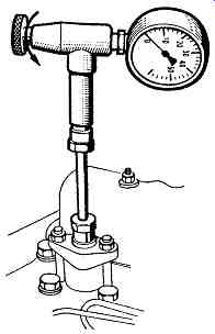
FIG. 8 Cylinder compressor gauge and adapter. Peugeot.
Combustion pressure and heat can be controlled by routine injector service (dribbling injectors load the cylinders with fuel), attention to timing, and conservative pump settings. Cooling system maintenance usually stops when the temperature gauge needle remains on the right of center. But local overheating is as critical as radiator temperature and is rarely addressed. According to engineers at Detroit Diesel, 1/4 in. of scale in the water jacket is the thermal equivalent of 4 in. of cast iron. Eroded coolant deflectors and rounded-off water pump impeller blades can also produce local overheating, which won’t register as a rise in header-tank temperature.
Local overheating on air-cooled engines can usually be traced to dirty, grease clogged fins or to loose shrouding.
Gasket life can be extended by doing what can be reasonably done to minimize potential leak paths. As explained below, some imperfection of the head and fire deck seating surfaces must, as a practical matter, be tolerated. Fasteners should be torqued down to specifications and in the suggested torque sequence, which varies between engine makes and models. Asbestos gaskets, without wire or elastomer reinforcements, "take a set" and must be periodically retightened. Newer, reinforced gaskets hold initial torque, but proper diesel maintenance entails retightening head bolts periodically.
Disassembly
The drill varies between makes and models, and is described in the manufacturer's manual. Here, I merely wish to add some general information, which might not be included in the factory literature.
It’s good and sometimes necessary practice to align the timing marks before the head is dismantled. Bar crankshaft over-in its normal direction of travel-to tdc on No. 1 cylinder compression stroke. Tdc will be referenced on the harmonic balancer or flywheel; the compression stroke will be signaled by closed intake and exhaust valves on No. 1 cylinder. In most cases, the logic of timing marks on overhead cam and unit injector engines will be obvious; when it’s not, as For example, when camshaft timing indexes a particular link of the drive chain, make careful notes.
A timing error on assembly can cost a set of valves.
Experienced mechanics don’t disassemble more than is necessary. Normally you will remove both manifolds, unit injector rocker mechanisms, and whatever hardware blocks access to the head bolts. Try to remove components in large bites, as assemblies, by lifting the intake manifold with turbocharger intact, removing the shaft-type rocker arms at the shaft hold-down bolts, and so on.
Miscellaneous hardware should remain attached, unless the head will be sent out for machine work. In this case, it should be stripped down to the valves and injector tubes. Otherwise, the head might be returned with parts and fasteners missing.
Note: Injector tubes on some DI heads extend beyond the head parting surface and, unless removed, might be damaged in handling.
Examine each part and fastener as it comes off. If disassembly is extensive, time will be saved by storing the components and associated fasteners in an orderly fashion.
You might wish to use plastic baggies, labeled with a Sharpie pen or Marks-A-Lot for this purpose. Keep the old gaskets for comparison with the replacements.

FIG. 9 Detroit Diesel Series 60 valves and injectors actuate from a single
overhead camshaft.
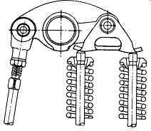
FIG. 10 Detroit Diesel dual valve actuating mechanism, used on the firm's
two-cycle engines.
Rocker assemblies
Two rocker arm configurations are used on OHV engines. Commercial and automotive engines developed from industrial engines generally pivot the rockers on single or double shafts, as illustrated several times in this section, including FIG. 6 and, as applied to ohc engines, in Figs. 9 and 10. The earlier drawing is the most typical, because a single rocker drives each intake and exhaust valve. Figures 9 and 10 illustrate Detroit Diesel solutions to the problem of driving two valves from the same rocker arm. Regardless of the rocker configuration, the hollow pivot shaft doubles as an oil gallery, distributing oil to the rocker bushings through radially drilled ports. Rockers are steel forgings, case-hardened on the valve end and generally include provision for valve lash adjustment.
Shaft-type rockers are detached from the head as an assembly with the shaft while the pushrods are still engaged. Note the lay of the shaft and rockers, and if no identification marks are present, tag the forward end of the shaft as an assembly reference. Loosen the hold-down bolts slowly, a half-turn or so at a time following the factory-recommended breakout sequence. If no information is provided on this point, work from the center bolt outward. This procedure will distribute valve spring forces over the length of the shaft.
Set the rocker arm assembly aside and remove the pushrods, racking them in the order of removal with the cam-ends down. A length of four-by-four, drilled to accept the pushrods and with the front of the engine clearly marked, makes an inexpensive rack.
Although the task is formidable on a large engine, the rocker arms, together with spacers, locating springs, and wave washers, should be completely disassembled for cleaning and inspection. Critical areas are:
• Adjusting screws-check the thread fit and screw tips. Screws are case-hardened: once the carburized "skin" is penetrated, it will be impossible to keep the valves adjusted.
• Rocker tips-with proper equipment, worn tips can usually be re-contoured, quieting the engine.
• Rocker flanks-check for cracks radiating out from the fulcrum. Cracks tend to develop on the undersides of the rockers at the fillets.
• Bushings-wear concentrates on the engine side of the bushing and, when severe, is accompanied with severe scoring, which almost always involves the shaft. Clearance between the bushing and an unworn part of the shaft should be on the order of 0.002 in. Replacement bushings are generally available from the original equipment manufacture (OEM) or aftermarket. The old bushing is driven out with a suitable punch, and the replacement pressed into place and reamed to finish size. Aligning the bushing oil port with the rocker arm port is, of course, critical.
• Shaft-inspect the surface finish, mike bearing diameters, and carefully clean the shaft inner diameter (ID), clearing the oil ports with a drill bit. Do the same for the oil supply circuit. Rocker arms are remote from the pump, and lubrication is problematic.
Small engines in general and automotive plants derived from SI engines use pedestal-type rockers, of the type illustrated in FIG. 11. This technology, pioneered by Chevrolet in 1955, represents a considerable cost saving because the pivots compensate for dimensional inaccuracies and the rockers are steel stampings. Most examples lubricate through hollow pushrods. If rockers are removed, it’s vital that they be assembled as originally found, together with fulcrum pieces and hold-down hardware. Rack the pushrods as described in the previous paragraph.
The locknuts that secure the rockers to their studs should be renewed whenever the head is serviced. Other critical items are
• Studs-check for thread wear, nicks, distortion, and separation from the head. As far as I am aware, all diesel pedestal-type rocker studs thread into the cylinder head.
• Rocker pivots-the rocker pivots on a ball or a cylindrical bearing, secured by the stud nut, and known as the fulcrum seat ( FIG. 12A). Reject the rocker, if either part is discolored, scored, or heat checked. How much wear is permissible on the rocker pivot is a judgment call.
• Fasteners-replace locknuts if nut threads show low resistance to turning, or for the considerable insurance value. Replace stud nuts if faces exhibit fractures ( FIG. 12B).
• Rocker tips-look for evidence of impact damage that could point to a failed hydraulic lifter and possible valve tip, valve guide, or pushrod damage. For want of a better rule, replace the rocker when tip wear is severe enough to hang a fingernail.
Pushrods
Inspect the push rod for wear on the tips and for bends. The best way to determine trueness is to roll the rods on a machined surface or a piece of optically flat plate glass.
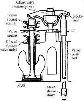
FIG. 11 Pedestal-type rocker arm, pivots on an adjustable fulcrum for lash
adjustment. Onan
Valve lifters
Valve lifters, or tappets, are serviced at this time when the lifters are driven from an overhead camshaft or when battered rocker arm tips indicate the need. It should be mentioned that GM 350 hydraulic lifters must be bled down before the cylinder head is reinstalled. Factory manuals recommend that lifters be collapsed twice, the second time 45 minutes after the first. According to technicians familiar with these engines, the factory is not kidding.

FIG. 12 Rocker arm assembly and nomenclature (A); stud nut wear pattern (B).
Ford Motor Co.
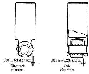
FIG. 13 Roller tappet, with wear limits. General Motors Corp.
FIG. 13 illustrates the roller tappet used on GM two-cycle engines. This part is subject to severe forces and, in the typical applications, experiences fairly high wear rates. Inspect the roller for scuffing, flat spots, and ease of rotation. Damage to the roller OD almost always is mirrored on the camshaft.
Roller and pin replacement offers no challenge, but lubrication is critical. During the first few seconds of operation, the only lubrications the follower receives is what you provide. Engine-supplied lube oil is slow to find its way between the roller and pin.
Ensure proper lubrication by removing the preservative from new parts with Cindol 1705; clean used parts with the same product. Just before installation, soak the followers in a bath of warm (100 degrees – 125 degrees F) Cindol. Turn the rollers to release trapped air.
Install with the oil port at the bottom of the follower pointed away from the valves.
There should be 0.005-in. clearance between the follower legs and guide. The easiest way to make this adjustment is to loosen the bolts slightly and tap the ends of the guide with a brass drift. Bolts should be torqued to 12-15 ft-lb.
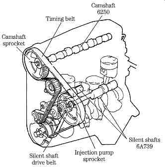
FIG. 14 Ford 2.3L turbo is a new design that employs a cogged (or Gilmer)
belt for camshaft drive. Gilmer belts might fail without obvious warning and
should be replaced on a rigid engine-hours or mileage schedule. Belts must
be tensioned as described by the engine maker and should not be subjected to
reverse rotation. Baring the engine backwards can shear or severely damage
the teeth.
Overhead camshafts
Disengage the drive chain or belt ( FIG. 14). Camshaft mounting provisions vary; some ride in split bearings and are lifted vertically, others slip into full-circle bearings and might require a special tool to open the valves temporarily for lobe clearance during camshaft withdrawal. Split bearing journals must be assembled exactly as originally found. Make certain that bearing caps are clearly marked for number and orientation. Loosen the caps one at a time, working progressively from the center cap out to the ends of the shaft. (Center, first cap right of center, first cap left of center, second cap right of center, and so on.)

FIG. 15 Peek-a-boo head bolts hide under pipe plugs on GM 350 engines. Upon
assembly, plug threads should be coated with sealant. Fel-Pro, Inc.
Head bolts
Head bolts should now be accessible, but not always visible. Olds 350 engines hide three of the bolts under pipe plugs ( FIG. 15); some Japanese engines secure the timing cover to the head with small-diameter bolts that, more often than not, are submerged in a pool of oil.
The practice of using an impact wrench on head bolts should be discouraged.
A far better procedure and one that must be used on aluminum engines is to loosen the bolts by hand in three stages and in the pattern suggested by the manufacturer.
Make careful note of variations in bolt length and be alert for the presence of sealant on the threads. Sealant means that the bolt bottoms into the water jacket, a weight saving technique inherited from SI engines.
Note: To prevent warpage, the head must be cold before the bolts are loosened.
Clean the bolts and examine carefully for pulled threads, cracks (usually under the heads), bends, and signs of bottoming. Engines have come off the line with short bolt holes.
GM and a few other manufacturers use torque-to-yield bolts, most of which are throwaway items. When this is the case, new bolts should be included as part of the gasket set.
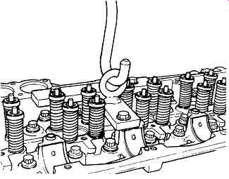
FIG. 16 Lift brackets should be at the approximate center of gravity of the
casting, so that the head lifts vertically off its alignment pins. Detroit
Diesel
Lifting
Large cylinder heads require a lifting tackle and proper attachment hardware ( FIG. 16); heads small enough to be manhandled might need a sharp blow with a rubber mallet to break the gasket seal. Lift vertically to clear the alignment pins, which are almost always present.
Mount the head in a holding fixture ( FIG. 17), or lacking that, support it on wood blocks.
Valves
Valves are removed by compressing the springs just far enough to disengage the keepers, or valve locks ( FIG. 18). It’s good practice to replace valve rotators, shown in FIG. 7. Seals ( FIG. 19) should also be renewed. Specify high tempera ture Viton for the seal material.
If all is right, the valves will drop out of their guides from their own weight. The usual cause of valve bind is a mushroomed tip, which can be dressed smooth with a stone and which means that the engine has been operating with excessive lash.
The associated camshaft lobe might be damaged. A bent valve suggests guide seizure or piston collision.

FIG. 17 Cylinder head holding fixture. Marine Engine Div., Chrysler Corp.
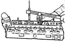
FIG. 18 Lever-type valve spring compressor.
Cleaning
Cleaning techniques depend on the available facilities. In the field, cleanup usually consists of washing the parts in kerosene or diesel fuel. Gasket fragments can be scraped off with a dull knife (a linoleum knife with the blade ground square to the handle is an ideal tool). The work can be speeded up by using one of the aerosol preparations that promise to dissolve gaskets. In general, it’s not a good practice to use a wire brush on head and cooling system gaskets that, until recently, contained asbestos. Sealant, sometimes used in lieu of conventional valve cover and cooling sys tem gaskets, can be removed with 4 in. 3M Scotch-Brite Surface Conditioning Discs, mounted on a high-speed die grinder. Use the coarse pad (3M 07450) on steel surfaces, the medium (3M 07451) on aluminum.
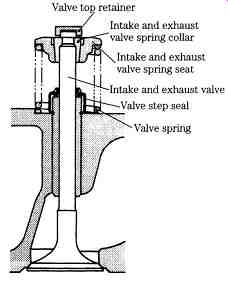
FIG. 19 Yanmar valves employ umbrella-type seals.
Carbon responds to a dull knife and an end-cutting wire wheel. Clean the piston tops, rotating the crank as necessary. Overhead camshaft drive chains will foul if the crankshaft is turned, and one cannot pretend to do much by way of piston cleaning on these engines.
Machine shops and large-scale repair depots employ less labor-intensive methods.
Some shops still use chlorinated hydrocarbons (such as perchloroethylene and trichloroethylene) for degreasing, although the toxicity of these products has limited their application. A peculiar side effect of trichloroethylene (TCE) exposure is "degreaser's flush." After several weeks of contact with the solvent, consumption of alcohol will raise large red welts on the hapless degreaser's face.
Once the head (and other major castings) are degreased, ferrous parts are traditionally "hot-tanked" in a caustic solution, heated nearly to the boiling point. Caustic will remove most carbon, paint, and water-jacket scale. Parts are then flushed with fresh water and dried. In the past, some field mechanics soaked iron heads in a mild solution of oxalic acid to remove scale and corrosion from the coolant passages.
Caustic and other chemical cleaners pose environmental hazards and generate an open-ended liability problem. The Environmental Protection Agency holds the producer of waste responsible for its ultimate disposition. This responsibility cannot be circum vented by contract; if a shop contracts for caustic to be transported to a hazardous waste site, and the material ends up on a country road somewhere, the shop is liable.
Consequently, other cleaning technologies have been developed. Pollution Control Products is perhaps the best-known manufacturer of cleaning furnaces and claims to have more than 1500 units in service. These devices burn natural gas, propane, or No. 2 fuel oil at rates of up to 300,000 Btu/hour to produce temperatures of up to 800 degr. F. (Somewhat lower temperatures are recommended for cylinder heads and blocks.) An afterburner consumes the smoke effectively enough to meet EPA emission, OSHA workplace safety, and most local fire codes.

FIG. 20 Walker Peenmatic shot blaster adds an "as-new" finish used
casting.
Such furnaces significantly reduce the liability associated with handling and disposal of hazardous materials, but are not, in themselves, the complete answer to parts stripping. Most scale flakes off, but some carbon, calcified gasket material, and paint might remain after cleaning.
Final cleanup requires a shot blaster such as the Walker Peenimpac machine illustrated in Fig, 7-20. Parts to be cleaned are placed on a turntable inside the machine and bombarded with high-velocity shot. Shot size and composition determine the surface finish; small diameter steel shot gives aluminum castings a mat finish, larger diameter steel shot dresses iron castings to an as-poured finish. Delicate parts are cleaned with glass beads.
Head casting
Make a careful examination of the parting surfaces on both the head and block, looking for fret marks, highly polished areas, erosion around water-jacket ports, and scores that would compromise the gasket seal.
The next step is to determine the degree of head distortion, using a machinist's straightedge and feeler gauges, as illustrated in FIG. 21. Distortion limits vary with the application and range from as little as 0.003-0.008 in. or so. In theory, the block deck has the same importance as the head deck; in practice, a warped block would not be welcome news when head work was all that was contemplated, and most mechanics let sleeping dogs lie.
However head bolt holes deserve special attention. Be alert for:
• Stripped threads-strip-outs can be repaired with Heli-Coil inserts. It’s rare to find more than one bolt hole stripped; if the problem is endemic, check with the manufacturer's technical representative on the advisability of using multiple inserts. At least one manufacturer restricts the number of Heli-Coils per engine and per cylinder.
• Pulled threads-this condition, characterized by slight eruption in the block metal adjacent to the bolt holes, can be cured by chamfering the uppermost threads with an oversized drill bit or countersink. Limit the depth of cut to one or two threads.
• Dirty threads-chase head bolt and other critical threads with the appropriate tap. In theory, one should use a bottoming tap, recognized by its straight pro file and squared tip. In practice, one will be lucky to find any tap for certain metric head bolt threads, which are pitched differently than the run of International Standards Organization (ISO) fasteners. Also realize that "bar gain" taps can, because of dimensional inaccuracies, do more harm than good. Blow out any coolant that has spilled into the bolt holes with com pressed air, protecting your eyes from the debris.
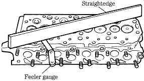
FIG. 21 Head warp should be checked in three planes: diagonally as shown,
longitudinally, and transversely with particular attention to areas between
combustion chambers. Ford Motor Co.
Head resurfacing
Minor surface flaws and moderate distortion can usually be corrected by resurfacing, or "milling." However, there are limits to how much metal can be safely removed from either the head or the block. These limits are imposed by the need to maintain piston-to-valve clearance and, on overhead cam engines, restraints imposed by the valve actuating gear. The last point needs some amplification. Reducing the thickness of the head retards valve timing when the camshaft receives power through a chain or belt. Retarded valve timing shifts the torque curve higher on the rpm band.
The power will still be there, but it will be later in coming. The effect of lowering a gear-driven camshaft is less ambiguous; the gears converge and ultimately jam.
Fire deck spacer plates are available for some engines to minimize these effects, and ferrous heads have been salvaged by metal spraying. These options are worth investigating, but one is usually better off following factory recommendations for head resurfacing, as in other matters.
The minimum head thickness specification, expressed either as a direct measurement between the fire deck and some prominent feature on the top of the casting or as the amount of material that can be safely removed from the head and block. Detroit Diesel allows 0.020 in. on four-cycle cylinder heads and a total of 0.030 in. on both the heads and block. Other manufacturers are not so generous, especially on light- and medium-duty engines. For example, the head thickness on Navistar 6.9L engines (measured between the fire deck and valve cover rail) must be maintained at between 4.795 and 4.805 in., a figure that, when manufacturing tolerances are factored in, practically eliminates the possibility of resurfacing. As delivered, the exhaust valve might come within 0.009 in. of the piston crown, and the piston crown clears the roof of the combustion chamber by 0.025 in. Admittedly, these are minimum specifications, but it’s difficult to believe that any 6.9L can afford to lose much fire deck metal. Navistar's 9.0L engine, the Ford 2.2L, and the Volkswagen 1.6L engines simply cannot be resurfaced and remain within factory guidelines. Thicker-than-stock head gaskets are available for the VW, but are intended merely to compensate for variations in piston protrusion above the fire deck.
The cardinal rule of this and other machining operations is to remove as little metal as possible, while staying within factory limits. Minor imperfections (such as gasket frets and corrosion on the edges of water jacket holes,) should be brazed slightly overflush before the head is milled.
Pre-combustion chambers, or precups, are pressed into the head or Caterpillar engines, threaded in. In some cases, precups can remain installed during resurfacing; others must be removed and (usually) machined in a separate operation ( FIG. 22) When it’s necessary to replace injector tubes, the work is done after the head has been resurfaced and is always followed by a pressure test.
Note: Ceramic precups are integral components, serviced by replacing the head.
Most shops rely on a blanchard grinder, such as the one shown in FIG. 23 for routine resurfacing. Heavier cuts of 0.015 in. or more call for a rotary broach, known in the trade as a "mill." When set up correctly, a mill will give better accuracy than is obtainable with a grinder. Some shops, especially those in production work, use a movable belt grinder. These machines are relatively inexpensive, require zero set-up time, and produce an unsurpassed finish. However, current belt grinders, which sup port the workpiece on a rubber platen, are less accurate than blanchard grinders.
Typically, iron heads like a dead smooth surface finish in the range of 60 and 75 rms (root mean square). Some machinists believe that a rougher finish provides the requisite "tooth" for gasket purchase, although there is little evidence to support the contention.

FIG. 23 A blanchard grinder is used for light head milling, manifold milling,
and other jobs where some loss of precision can be tolerated.
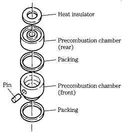
FIG. 22 Precombustion chamber and gaskets. An installed precup is shown in
FIG. 15. Yanmar Diesel Engine Co. Ltd.
Crack detection
Cylinder heads should be crack tested before and after resurfacing. The apparatus used for ferrous parts generates a powerful magnetic field that passes through the part under test. Cracks and other discontinuities at right angles to the field become polarized and reveal their presence by attracting iron filings. The magnetic particle test, known generically by the trade name Magnaflux, is useful within its limits. It cannot detect subsurface flaws, nor does it work on nonferrous metals. But fatigue and thermal cracks always start at the surface, and will be seen.
Nonferrous parts are tested with a penetrant dye ( FIG. 24). A special dye is sprayed on the part, the excess is wiped off, and the part is treated with a developer that draws the dye to the surface, outlining the cracks. In general, penetrant dye is considered less accurate than Magnaflux, but, short of x-ray, it remains the best method available for detecting flaws in aluminum and other nonmagnetic parts.
Neither of these detection methods discriminates between critical and superficial cracks. The cylinder head might be fractured in a dozen places and still be serviceable.
But cracks that extend across a pressure regime-that is, from the combustion chamber, cylinder bore, water jacket, or oil circuits-require attention.
Mack and a handful of other manufacturers build surface discontinuities into the roofs of the combustion chambers, which appear as cracks under Magnafluxing, but which are intended to stop crack propagation. These built-in "flaws" run true and straight, in contrast to the meandering paths followed by the genuine article. In general, cracks that are less than a 1/ 2 in. long and don’t extend into the valve seat area might be less serious than they appear. Short cracks radiating out from precombustion chamber orifices can also be disregarded.
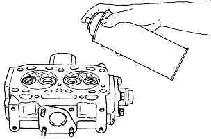
FIG. 24 Penetrant dye detects cracks in nonferrous parts, a category that
includes Valve heads. Yanmar Diesel Engine Co. Ltd.
Crack repairs
Assuming that both ends of the crack are visible, it’s normally possible to salvage an iron head by gas welding. For best results, the casting should be preheated to 1200 degrees F. Skilled TIG practitioners can do the same for aluminum heads.
Some shops prefer to use one of several patented "cold stitching" processes on iron castings. The technician drills holes at each end of the crack (to block further propagation) and hammers soft iron plugs into the void, which are then ground flush. The plugs must not be allowed to obstruct coolant passages.
Metal spraying is demonstrated to have utility, but rarely practiced.
Pressure testing
FIG. 25 illustrates a Detroit Diesel cylinder head, partially dressed out for pressure testing. At this point, most shops would introduce high-pressure water into the jacket and look for leaks, which might take the form of barely perceptible seep age. Detroit Diesel suggests that air be used as the working fluid. Their approach calls for pressurizing the head to 30 psi and immersing the casting in hot (200 degr. F) water for 30 minutes. Leaks register as bubbles.
Straightening
Aluminum heads usually carry the camshaft and are often mounted to a cast-iron block. The marriage is barely compatible. Aluminum has a thermal coefficient of expansion four times greater than that of iron. Even at normal temperatures, the head casting "creeps," with most of the movement occurring in the long axis ( FIG. 26).
Pinned at its ends by bolts, the head bows upward-sometimes as much as 0.080 in.
The camshaft cannot tolerate misalignments of such magnitude and, if it does not bend, binds in the center bearings.
Such heads are best straightened by stress relieving. The process can be summarized as follows: the head is bolted to a heavy steel plate, which has been drilled and tapped to accommodate the center head bolts. Shims, approximately half the thickness of the bow, are placed under the ends of the head, and the center bolts are lightly run down. Four or five hours of heat soak, followed by a slow cool down, usually restores the deck to within 0.010 in. of true. Camshaft bearings are less amenable to this treatment, and will require line boring or honing.
Corrosion can be a serious problem for aluminum heads, transforming the water jacket into something resembling papier-mâché. Upon investigation, one often finds that the grounding strap-the pleated ribbon cable connecting the head to the firewall-was not installed.

FIG. 25 The water jacket should be sealed as shown, pressurized to about
30 psi, and immersed in hot water. Bubbles indicate the presence of cracks.
 FIG. 26 Thermal expansion of an aluminum head is about four times greater
than for a cast iron block. Something must give. Fel-Pro, Inc.
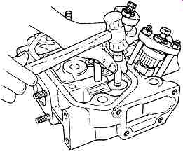
FIG. 28 Valve guides are installed to a specified depth by means of a factory-supplied
driver. Yanmar Diesel Engine Co. Ltd.
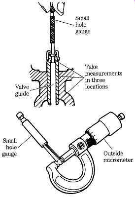
FIG. 27 A split-ball gauge, used to determine guide wear. Ford Motor Co.
Valve guides
Rocker-arm geometry generates a side force, tilting the valves outward and wearing away the upper and lower ends of the guides. The loss of a sharp edge at the lower end of the guides encourages carbon buildup and accelerates stem wear; the bellmouth at the upper end catches oil, which then enters the cylinder. FIG. 27 illustrates a split ball gauge used to determine guide ID.
Nearly all engines employ replaceable guides or, if lacking that, have enough "meat" in the casting to accept replaceable guides ( FIG. 28). A Pep replacement guide for 0.375-in. valve stem measures 0.502 in. on the OD. The BMW 2.4L engine is one of the few for which replacement guides are not available. However, the integral (i.e., block metal) guides can be reamed to accept valves with oversized stems. The GM 350 offers the option of replaceable guides, plus oversized stems The latter are apparently a manufacturing convenience and such parts are difficult to come by.
Old guides drive out with a punch, and new guides install with a driver sized to pilot on the guide ID ( FIG. 28). Cast-iron heads can be worked cold, but a careful technician will heat aluminum heads so that the guide bores don’t gall. Engine manufacturers seem to prefer perlitic cast-iron or iron-alloy guides; many machinists claim phosphor bronze has better wearing qualities. Whatever the material, replacement guides rarely are concentric with the valve seat, and some corrective machine work is almost always in order. Stem-to-guide clearances vary with engine type and service; light- and medium-duty engines will remain oil-tight longer with a 0.0015-in. clearance.
Heavy-duty engines, which run for long periods at hall rated power, need to be set up looser-as much as 0.005 in. when sodium-cooled valves are fitted.
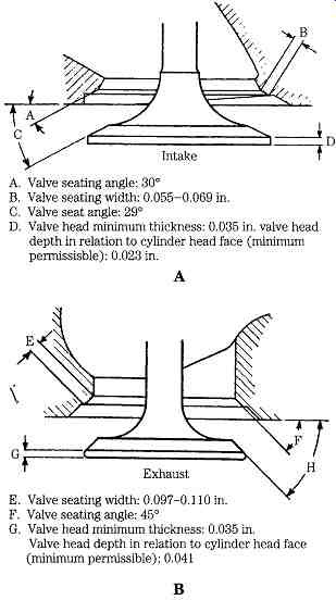
FIG. 29 Typical valve specifications, Bedford engines.
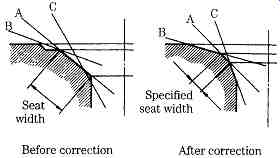
FIG. 30 Valve seat details-Yanmar GM series engines.
Valve service
Stem and guide problems can be the result of wear or carbon and gum accumulations that hold the valve open against spring pressure. These deposits are caused by the wrong type of lubricant, ethylene glycol leakage into the sump, and low coolant temperatures (below 160 degr. F). Low temperatures are usually the result of long periods at idle and aggravate any mismatch between fuel characteristics and engine demands. Fuel that burns cleanly at normal temperatures can gum the guide and carbon over the valve heads when the engine runs consistently cool. Sticking can also be caused by bent stems.
Premature valve burning, which in extreme cases torches out segments of valve face and seat, has one cause: excessive heat. This can be the result of abnormal combustion chamber temperatures or of a failure of the cooling system. Faulty injector timing and failure of the exhaust gas recirculation (EGR) and sustained high speed/ high-load operation system will create high cylinder temperatures. The thermal path from the valve face to the water jacket can be blocked by insufficient lash (which holds the valve off its relatively cool seat), local water-jacket corrosion, or a mal function associated with flow directors. Also known as diverters, flow directors are inserted into the water jacket to channel coolant to the valve seats and injector sleeves. These parts can corrode or vibrate loose. Of course, a generalized failure of the cooling system, affecting all cylinders, is possible.
Valve breakage usually takes the form of fatigue failure from repeated shock loads or bending forces. Fatigue failure leaves a series of rings, not unlike tree growth rings, on the parting surfaces. Shock loads are caused by excessive valve lash, which slams the valve face against the seat, or weak valve springs. Bending forces are generated if the seat and/or guide is not concentric with the valve face.
The most dramatic form of valve failure comes about because of collision with the piston. As mentioned previously, Navistar allows as little as 0.009 in. between the exhaust valve and the piston crown at convergence, which occurs 4 ¼ degrees btdc.
Admittedly, the 6.9 is a "tight" engine, but no diesel will tolerate excessive valve lash, weak valve springs, or overspeeding.
Valve service involves two operations, both of which are done by machine. The face is reground to the specified angle, which is usually (but not always) 30 degr. on the intake and 45 degr. on the exhaust, less a small angle, usually about 1.5 degr. . Thus, the 30 degr. intake seats specified for Bedford engines ( FIG. 29) would be cut to 28.5 degr. . A valve face grinder adjusts to any angle. Seats are cut true to specification, which creates a slight mismatch, known as the interference angle. Once the engine starts, valve faces pound into conformity with the seats. The interference angle ensures a gastight seal on initial start-up and eliminates the need for lapping.
Seats are typically ground in three angles: entry (which ranges from about 60 degr. -70 degr. ), seat, and exit (which is usually 15 degr. ). Thus seat width can be controlled by undercutting either of the flanking angles ( FIG. 30). The seat should center on the valve face.
Valve protrusion or, as the case might be, recession, must be held to tight limits on these engines. A valve that extends too far into the chamber might be struck by the piston; one that is sunk into its seat hinders the combustion process, sometimes critically. FIG. 31 illustrates how the measurement is made. Recession can be cured by replacing the valve and/or seat. Protrusion is a more difficult problem, encountered when the head has been resurfaced; a deep valve grind might help, provided one has the requisite seat thickness and can tolerate the increase in installed valve height (see immediately below). A handful of OEMs supply thinner-than-stock seat inserts. These inserts require corresponding thicker valve spring seats or shims, in order to maintain valve spring tension. Ultimately, one might be forced to replace the cylinder head.
Installed valve height, measured from the valve seat to the underside of the spring retainer, or cap, has become increasingly significant ( FIG. 32). Springs on newer engines come perilously close to coil bind with as little as 0.005 in. separating the coils in the full open position.
Finally, the machinist dresses the valve stem tip square to restore rocker-tip to increase available contact area and to center hydraulic-lifter pistons. The average lifter has a stroke of 0.150 in. If the plunger is centered, available travel is 0.075 in., before it bottoms and holds the valve off its seat. But it’s rare to find new engines with precisely centered lifter plungers, and available stroke might be considerably less than indicated. Deep valve grinding, head and block resurfacing, and camshaft grinding will, unless compensated for, collapse the lifters. The machinist can remove about 0.030 in. from the tip without penetrating the case hardening. Another limiting factor is rocker/spring-cap contact.
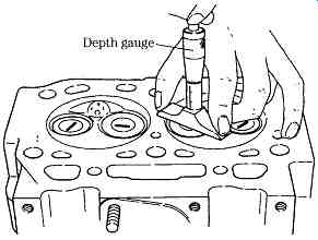
FIG. 31 A technician measures valve protrusion with a depth micrometer. Yanmar
Diesel Engine Co., Ltd.
Seat replacement
Valve seat inserts are pressed into recesses machined into the head. (Some very early engines used spigoted inserts with mixed results.) Seats must be replaced when severely burned, cracked, loose, or as a means of obtaining the correct valve protrusion. Many shops routinely replace seats during an overhaul for the insurance value.
Seats in iron heads are customarily driven out with a punch inserted through the ports, although more elegant tools are available ( FIG. 33); seats in aluminum heads should be cut out to prevent damage to the recess ( FIG. 34).
While new seats can be installed in the original counterbores, it’s good practice to machine the bores to the next oversize. Replacement seats for most engines are available in 0.010-, 0.015-, 0.020-, and 0.030-in. oversizes. Material determines the fit: iron seats in iron heads require about 0.005-in. interference fit; Stellite expands less with heat, and seats made of this material should be set up a little tighter; seats in aluminum require something on the order of 0.008-in. interference.
Seat concentricity should be checked with a dial indicator mounted in a fixture that pilots on the valve guide. Often the technician finds it necessary to restore concentricity by lightly grinding the seat.
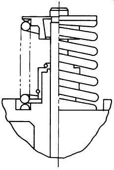
FIG. 32 Installed valve height is the distance between the spring seat and
the underside of the spring retainer. Often the factory neglects to provide
the specification, and it must be determined by direct measurement during disassembly.
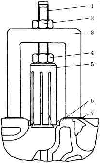
FIG. 33 Chrysler-Nissan supplies this valve seat puller. The split jaws (5)
can open as the nut (4) is tightened. Tightening the upper nut (2) lifts the
seat.
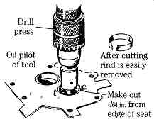
FIG. 34 Seats in aluminum heads should be machined out, rather than forced
out. Onan
Springs
Valve spring tension is all that keeps the valves from hitting the pistons. A "swallowed" valve is the mechanic's equivalent of the great Lisbon earthquake or the gas blowout at King Christian Island, which illuminated the Arctic night for eight months and could be seen from the moon. Thus, I suggest that valve springs be replaced (regardless of apparent condition) during upper engine overhauls.
If springs are to be used, inspect as follows:
• Carefully examine the springs for pitting, flaking, and flattened ends.
• Measure spring freestanding height and compare with the factory wear limit.
• Stand the springs on their ends and, using a feeler gauge and machinist's square, determine the offset of the uppermost coil ( FIG. 35). Compare with the factory specification (in angular terms, maximum allowable tilt rarely exceeds 2 degrees). Most keeper failures arise from unequal loading.
• Verify that spring tension falls within factory-recommended norms. FIG. 36 illustrates the tool generally used to make this determination.
Valve spring shims have appropriate uses, chiefly to restore the spring preload lost when heads and valve seats are refurbished. But shims should not be used as a tonic for tired springs, because the fix is temporary and can result in coil bind.
Most engine makers provide a linear valve spring tilt specification; Yanmar is more sophisticated. First spring free length is determined as shown in the left-hand drawing. The amount of offset is measured with a machinist's square. Offset (B) divided by free length (A) gives the specification, which for one engine series must not exceed 0.0035 in.

FIG. 36 Most valve spring testers measure force with a torque wrench. Ford
Motor Co.
Top clearance
Top clearance, or the piston-to-head clearance at tdc, is critical. Unfortunately, the position of piston crown varies somewhat between cylinders because of the stacked tolerances at the crankshaft, rod, piston pin bosses, and deck (which might be tilted relative to the crankshaft centerline). No two pistons have the same spatial relationship to the upper deck. Resurfacing, or decking, the block lowers the fire deck 0.010 in. or more with no better accuracy than obtained by the factory.
Most manufacturers arrive at top clearance indirectly by means of a piston deck height specification. Either of these measurements must be made when...
• the block is resurfaced.
• the manufacturer supplies replacement head gaskets in varying thickness to compensate for production variations.
The geometry of some engines (flat pistons and access to the piston top with head in place) invites direct measurement of top clearance. The cylinder head is installed and torqued, using a new gasket of indeterminate thickness. The mechanic then removes No. 1 cylinder glow plug and inserts the end of a piece of soft wire, known as fuse wire, into the chamber. Turning the flywheel through tdc flattens the wire between the piston crown and cylinder head. Wire thickness equals top clearance, or piston deck height plus compressed gasket thickness ( FIG. 37).

FIG. 37 Top clearance equals piston deck height plus the thickness of the
compressed head gasket. Yanmar Diesel Engine Co. Ltd.
Scrupulous engine builders sometimes make the same determination using modeling clay as the medium. Upon disassembly the clay is removed and carefully miked. This method applies equally well to flat and domed pistons.
The more usual approach is to measure piston deck height with a dial indicator.
The procedure involves three measurements, detailed as follows:
1. Zero the dial indicator on the fire deck, with the piston down (left-hand portion of FIG. 38).
2. Position the indicator over a designated part of the piston crown, shown as A in FIG. 38.
3. Turn the crankshaft in the normal direction of rotation through tdc. Note the highest indicator reading.
4. Repeat Step 3, taking the measurement at B.
5. Average measurements A and B.
6. Repeat the process for each piston. Use the piston with the highest average deck height to determine the thickness of the replacement head gasket.

FIG. 39 Cylinder head torque sequence.
Assembly
The manufacturer's manual provides detailed assembly instructions but includes little about the things that can go wrong. Most assembly errors can be categorized as follows:
• Insufficient lubrication. Heavily oil sliding and reciprocating parts, lightly oil head bolts and other fasteners, except those that penetrate into the water jacket. These fasteners should be sealed with Permatex No. 2 or the high-tech equivalent.
• Reversed orientation. Most head gaskets, many head bolt washers, and all thermostats are asymmetrical.
• Mechanical damage. Run fasteners down in approved torque sequences and in three steps-1/2, 2/3, and 1/1 torque ( FIG. 39). Exceptions are torque-to-yield head bolts and rocker arm shaft fasteners. The former are torqued as indicated by the manufacturer, whose instructions will be quite explicit. The latter- rocker shaft fasteners-should be brought down in very small increments, working from the center bolts out.
Gaskets, especially head gaskets, might also be damaged during assembly.
Lower the head on a pair of guide pins lightly threaded into the block. Pins can be fashioned from discarded head bolts by cutting the heads off. If pins are too short to extend through the head casting, slot the ends for screwdriver purchase.
Set initial valve lash adjustments, bleed the fuel system, start the engine. Final lash adjustments are usually made hot, after the engine has run for 20 minutes or so on the initial settings ( FIG. 40).

FIG. 40 Valve lash can be measured at any accessible point in the system.
For example, lash for the Ford-supplied 2.4L ohc is read as cam-to-rocker clearance
(A); Onan measures the clearance between rocker arm tip and valve stem (B).
Prev. | Next
Home top
of page Similar articles
