This section provides basic troubleshooting information that should help you narrow the source of the problem down to a particular system-fuel, air, starting, or exhaust.
Once this is done, turn to the section that deals with the system for additional troubleshooting and repair information.
The classic engine was essentially a mechanical device that failed in obvious ways.
A few simple tests were enough to establish the source of the difficulty. Newer engines are controlled by a computer. Sensors provide the computer with data on engine and environmental conditions, and actuators carry out the computer's commands, most of which are directed to the fueling system. Failure of any of these components-an erratic sensor, a slow-to-respond actuator, or a loose pin in the wiring harness-affects the way the engine runs. Serious failures, such as loss of the timing signal, shut the engine down.
These electronic engine management systems ( EMS) compensate, in part, for their complexity by setting trouble codes when the computer senses something is wrong. The first step in diagnosing computerized engines is to retrieve the trouble codes with the appropriate scan tool. The second step is to gather enough knowledge about the particular system to understand what the trouble codes mean.
Section 6 describes the functioning of these systems in some detail with emphasis on Caterpillar HEUIs and Ford Power Strokes. In other respects, computer-controlled engines are prone to the same malfunctions as precomputer models. Injector pumps fail, cylinders lose compression, head gaskets leak, and so on.
Again, let me stress that the first step in diagnosing EMS engines is to read the trouble codes. If you merely want to keep an eye on the condition of your engine, a $200 scanner that retrieves the codes and erases them with a push of the button is adequate.
If you are serious about repairing EMS engines, you will need to make a serious investment in tooling and documentation as described in Section 6. A professional-quality scanner will read active codes-those in effect now-and inactive, or historical, codes that have been set and later erased. The tool will also retrieve events a few seconds before and after each trouble code was set, shut down individual injectors, and report what the real-time data sensors transmit to the computer. Without these capabilities, you will be working blind.
Malfunctions
Common malfunctions are listed below together with probable causes and remedial actions. Fuel-related malfunctions can affect the color of the exhaust smoke, as indicated in TBL. 1. When taken together, engine behavior and smoke color provide a good indication of the source of the problem.
Engine cranks slowly, does not start
Starting system malfunction --High parasitic loads-- Crankshaft viscosity bound
Recharge batteries if cranking voltage drops below 9.5V or electrolyte reads less than 1.140 when tested with a hydrometer. Clean battery terminals. Perform starting system check ( Section 11).
Check for binds in driven equipment, overly tight drive belts, shaft misalignments.
Dark, sticky residue on the dipstick can indicate presence of antifreeze (ethylene glycol) in oil.
Have oil analyzed.
-- Engine cranks normally, does not start:
EMS sensor or actuator failure--No fuel to injectors--Contaminated fuel--Glow-plug failure--Air inlet restriction--Exhaust restriction--Loss of cylinder compression
Retrieve trouble codes. See Section 6.
Check for restrictions or air leaks in fuel system, low injector pressure.
Flush fuel system.
Check glow-plug supply circuit, glow-plug control module and individual plugs.
Replace air filter element.
Inspect piping, if necessary perform backpressure est.
Test cylinder compression.
--
Engine starts normally, runs no more than a minute or two, and shuts down:
Intermittent EMS-related R failure, bad harness connection Air in fuel B Fuel return line restricted Air inlet restriction Clogged fuel filter
Retrieve trouble codes. See Section 6.
Bleed system and check for air leaks.
Disconnect line to verify flow and remove obstruction.
Replace filter element.
Replace filter element.
---
Engine starts normally, misfires
EMS-related failure Air in fuel Air inlet or exhaust system restriction Clogged fuel filter Malfunctioning injector(s)
Loss of compression in one or C more cylinders
Retrieve trouble codes. See Section 6.
Bleed system, check for air leaks.
Replace air filter, check for excessive backpressure.
Replace filter element.
Replace injector(s).
Check cylinder compression.
--
Engine fails to develop normal power
EMS-related fault Insufficient fuel supply Contaminated fuel Injection timing error High-pressure fuel system malfunction Air inlet restriction Exhaust restriction Insufficient turbo boost Loss of engine compression
Retrieve trouble codes. See Section 6.
Replace filters, check transfer pump output, cap vent, and air in the system.
Verify fuel quality.
Check injector-pump timing.
inspect high-pressure fuel system for leaks and air entrapment. Verify pump output pressure. If necessary have pump recalibrated.
Change air-filter element.
inspect exhaust piping, test for excessive back pressure.
Change air-filter element, check boost pressure and for exhaust leaks upstream of the turbo.
Check engine cylinder compression.
=======
TBL. 1. Diagnosis by exhaust smoke color
Black or dark gray smoke
Symptom Probable cause Remedial action
Smokes under load, especially I at high and medium speed.
Engine quieter than normal.
Smokes under load, especially I at low and medium speed.
Engine noisier than normal.
Smokes under load at all speeds, W but most apparent at low and medium speeds. Engine may be difficult to start.
Smokes under load, especially at R high speed.
Smokes under load, noticeable T loss of power.
Smokes under load, especially at D high and medium speeds. Power may be down.
Smokes under load, especially at C low and medium speeds. Power may be down.
Puffs of black smoke, sometimes S with blue or white component.
Engine may knock.
Whitish or blue smoke at high I speed and light load, especially r when engine is cold. As temperature rises, smoke color changes to black. Power loss across the rpm band, especially at full throttle Whitish or blue smoke under light L load after engine reaches operating temperature. Knocking may be present
Blue smoke under acceleration L after prolonged period at idle. g Smoke may disappear under steady throttle.
Persistent blue smoke at all W speeds, loads and operating temperatures.
Light blue or whitish smoke at O high speed under light load.
Pungent odor.
---
Probable cause:
Injector pump timing retarded.
Injector pump timing advanced.
Weak cylinder compression.
Restricted air cleaner.
Turbocharger malfunction.
Dirty injector, nozzle(s).
Clogged/restricted fuel lines.
Sticking injectors.
Injector pump timing S retarded.
Leaking injector(s). Leaking valve seals.
Worn rings/cylinders.
Over-cooling.
---
Remedial action:
Set timing.
Set timing.
Repair engine.
Clean/replace air filter element.
Check boost pressure.
Clean/replace injectors.
Clean/replace fuel lines.
Repair/replace injectors.
Set timing.
Repair/replace injector(s).
Replace seals, check valve guides/stems.
Overhaul/rebuild engine.
Replace thermostat.
======
Tests
Fuel quality
Take a fuel sample from some convenient point upstream of the filter/water separator. Allow the fuel to settle for a few minutes in a glass container and inspect for cloudiness (an indication of water), algae (jellylike particles floating on the surface), and solids. Placing a few drops of fuel between two pieces of glass will make it easier to see impurities. If fuel appears contaminated, drain and purge the system as described below.
Assuming that the fuel is clean and water-free, the most important quality is its cetane value, which can be determined with fuel hydrometer. A good No. 2 diesel has a specific gravity of 0.840 or higher at 60_F. No. 1 diesel can reduce power out puts by as much as 7% over No. 2 fuel. Blending the two fuels, a common practice in cold climates, results in correspondingly less power.
Fuel system
Most failures involve the fuel system. This system consists of three circuits, each operating at a different pressure.
• Low-pressure circuit. This includes the tank strainer, in-tank pump (on many vehicles), water-fuel separator, filter(s), and lift pump. Pressures vary with the application, but rarely exceed 75 psi.
• Fuel-return circuit. Operating at almost zero pressure, the return line conveys surplus fuel from the injectors back to the tank, filter, or to the inlet side of injector pump. Many of these systems include a restrictor orifice between the fuel-supply line and the return line. The orifice can clog, closing off the fuel return. Air leaks become a matter of concern when fuel is returned to the filter or injector pump, and not to the tank.
• High-pressure circuit. As shown in FIG. 1, the high-pressure circuit connects the discharge side of the injector pump with the injectors. For many applications, the connecting plumbing takes the form of dedicated lines from pump to the individual injectors. A more modern approach is to supply the injectors from a common manifold, or rail. The third alternative does away with the external high-pressure circuit by employing unit injectors (UIs). Each UI is a self-contained unit, with its own high-pressure pump operated by an engine-driven camshaft or, in the case of the Hydraulic Electronic Unit Injector (HEUI), by oil pressure. The unit pump system (UPS) is a hybrid, with each injector served by a dedicated pump plunger operating off the engine camshaft. Plunger-to-injector lines are pressurized.

FIG. 1 This drawing illustrates the high-pressure circuits for four modern
fuel systems. From a mechanic's point of view, the UI system has much to recommend
it. High pressures are con fined within the injector bodies and failures tend
to be cylinder-specific. (Photo Bosch)
A mechanic has a duty to himself to know the pressures he is dealing with. Most, but not all, older-model engines had fuel systems that operated in the neighborhood of 6000-12,000 psi. But even at 6000 psi, fuel easily penetrates the skin (witness the speckled hands of old diesel mechanics) and often results in blood poisoning.
Common-rail and other modern systems generate pressures in excess of 20,000 psi, and the Honda 2.2-L, scheduled for introduction before 2009, develops 30,000 psi.
Pressures on this order cut to the bone and, if air bubbles are present, the fuel jets out like water from a hose.
WARNING: Wear eye protection and heavy gloves when working on diesel fuel systems of any vintage. Don’t attempt to disable modern ultrahigh-pressure injectors by cracking fuel-line connections.
Hydraulically actuated HEUI injectors shift the high-pressure regime to lube oil supplied at between 800 and 3300 psi, which is still a considerable pressure. These and other electronic injectors (recognized by the presence of wires running to them) pose the risk of electroshock. Injector voltages and amperages can be lethal.
WARNING: Don’t disconnect the wiring to electronic injectors while the engine is running.
For fuel to enter the cylinders, the h-p pump must generate enough pressure to unseat the injectors. Pop-off pressure, known more formally as NOP (nozzle opening pressure) or VOP (valve opening pressure), depends upon an unrestricted fuel supply. Air leaks or fuel blockages upstream of the pump, or failure of the pump itself can reduce delivery pressure below NOP. Electronic engine management systems keep close watch on delivery pressure and its effect on other variables, such as the concentration of oxygen in the exhaust. Low delivery pressure triggers one or more trouble codes.
Older, precomputer engines require a more proactive approach to determine if fuel is getting to the cylinders. One technique is to spray starting fluid into the air intake while cranking. If the engine starts, runs for few seconds and stalls, you can be reasonably confident that the problem lies in the fuel system.
CAUTION: Employ starting fluid with discretion. Large amounts of ether in the intake manifold or in the scavenging system on two-cycle engines can result in explosions powerful enough to break piston rings and bend connecting rods.
An alternative approach is to crank the engine over for a 20 or 30 seconds, and crack the fuel-supply line to one or more injectors. Fuel should be present. Note that this technique should be confined to older engines known to generate moderate fuel pressures of 6000 psi or so.
Bleeding
Bleeder screws or Schrader valves are located at high points in the filter assemblies ( FIG. 2) and in one or more locations on the accessible side of most injector pumps (Fig 3). Carefully clean the screws and adjacent areas to prevent foreign matter from entering the fuel circuit. Many engines have a hand-operated bleeder pump as part of the lift pump; others must be primed by cranking. Detroit Diesel supplies a portable hand-pump for engines not equipped with bleeder pumps.
Build a few psi of pressure in the system and, working from the tank forward, loosen the bleeder screws. Tighten the screws as soon as fuel flows in an uninterrupted stream. Run the engine for at least 20 minutes to ensure that the fuel system is completely purged. If the no-start or hard-start problem recurs after the engine has cooled down, the problem is almost surely an air leak in the low-pressure (injector pump-supply) circuit.
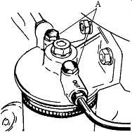
FIG. 2 Fuel filter bleed screws. Lehman Ford Diesel.
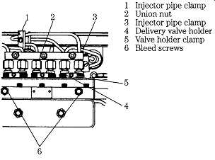
FIG. 3 Inline injection pump bleed screws. Ford Industrial Engine and Turbine
Operations.
Low-pressure circuit tests
Failure is most often associated with flow restrictions and air or fuel leaks, although failure of the lift pump is not unknown.
The tests that follow, developed by Ford for light trucks, locate flow restrictions by measuring the pressure drops across individual components while the engine is running. In other words, Ford uses the engine as a test bench. Other manufactures would have the mechanic disassemble the system and test each component separately. If you want to use the Ford approach-which has advantages-establish baseline pressure drops while the system is still healthy and operating normally.
Which gauge will be used depends upon the fuel-filter location relative to the lift pump. If the filter is located on the suction side of the lift pump, a 0-30 in.
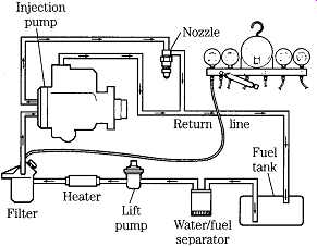
FIG. 4 Filter location relative to the lift pump determines whether a pressure
or vacuum gauge is used. In this example, the filter is on the outlet side
of the pump and sees positive pressure.
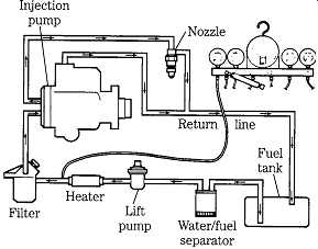
FIG. 5 The next step is to install the gauge at the input side of the filter.
The difference between output-side and input-side readings represents the pressure
drop across the filter.
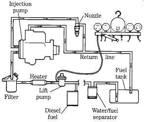
FIG. 6 When measuring lift-pump output, isolate the pump from suction-side
pressure drops by providing fuel from a separate source.
Hg vacuum gauge will be needed. If downstream of the pump, the Ford application calls for 0-15 psi pressure gauge. Other lift pumps develop higher pressures.
1. Connect the appropriate gauge at the output side of the filter ( FIG. 4). Start the engine and note the gauge reading at 2500 rpm.
2. Connect the gauge to the inlet side of the filter, repeat the test, and compare these readings against the pressure drop for a new filter (Fig 4-5).
3. Use the same procedure for detecting restrictions in the water/fuel separator, heater, and other components.
The lift pump, also known as the transfer or supply pump, moves fuel from the tank to the injector pump. FIG. 6 illustrates the Ford approach to measuring lift pump output pressure. A container of diesel fuel supplies the pump, thus isolating it from possible suction-side restrictions. However, it’s usually enough to connect the gauge in parallel with pump output.
Pump pressure is only part of the picture. Manufacturers should, but rarely do, provide volume specifications for this and other pumps. If you're familiar with the engine, some rough idea of output volume can be had by monitoring fuel flow leaving the return line.
Fuel leaks leave a trail, but some mechanics like to check connections with soapy water or the glycerin-based solutions used to detect Freon leaks.
Air can enter on the suction side of the lift pump or when voids develop in the solid column of fuel. The latter condition occurs if the tank runs dry, filter elements are changed or, after shutdown, when fuel cools and contracts in filter canisters.
Entrapped air causes the injector pump to lose prime. Symptoms include reluctance or outright refusal to start, and sudden shutdowns within seconds of starting.
Depending upon the amount of air intrusion, the engine may start more or less normally, but refuse to idle.
The time required for air to reach the injector pump gives an indication of the leak source. If the engine dies within seconds of starting, the source of the air must be nearby. Layouts vary, but common practice is to mount the filter and water separator in close proximity to the injector pump. Check these items first. Fuel-return lines that discharge into the filter or suction side of the injector pump present a major leak hazard.
Another technique is to insert a length of clear plastic fuel line of the type used on motorcycles between the lift and injector pumps ( FIG. 7) or at any location in the low-pressure circuit where leaks are suspected. Start the engine and look for bubbles in the fuel stream.
You can also test for air leaks by disconnecting the line at the tank and pump.
Plug one end and connect a hand pump or other source of low-pressure air to the free end. Pressurize to no more than 15 psi and apply soapy water or a commercial leak detector solution to the line connections, filter-canister parting surfaces, and other potential leak sources.
CAUTION: Don’t pressurize the fuel tank-it might rupture.
Once the leak has been found and repaired, renew o-ring seals on connections, assemble all threaded connections with Loctite 515 Gasket Eliminator, and bleed the system as described above.
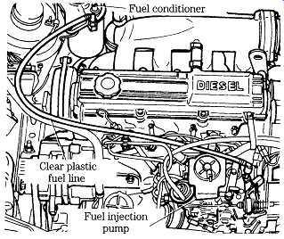
FIG. 7 A length of clear plastic tubing spliced into the fuel line between
the lift and injection pumps shows if air is present.
High-pressure circuit tests
High-pressure systems fail because of fuel leaks (air leaks are uncommon), mal functioning injectors, or inadequate pump pressure.
Fuel-pipe unions on engines with pump-fed injectors are a major leak source.
Loosening and retightening the union usually corrects the problem. See Section 5 for additional information.
Some engines are more prone to leakage than others. For example, hard-used White trucks tend to develop small leaks at the fuel delivery valves, located under the fuel-pipe connections on UTDS, APD, 6BB, T and Q series injector pumps. Replace the o-ring seal and copper ring gasket, and inspect lapped surfaces for channeling. The UTDS pumps in question develop more than 15,000 psi. Crimps or flattened spots in the fuel lines, over-fueling, and clogged injectors will further increase delivery pressure. WARNING: Wear eye protection and keep hands clear of high-pressure fuel spray. Use a piece of cardboard to detect leaks in hard-to-see places.
Current EM systems focus on overall performance, rather on events occurring within individual cylinders. These systems know when a cylinder goes down or when electronic injectors lose power, but are blind to the roughness and loss of responsiveness associated with skewed spray patterns, fuel dribble, and the like. For that we need more traditional methods.
Symptoms of injector failure include
• Ragged idle or misfiring at certain speeds
• Black, gray, or white smoke
• Vibration and knock
If the injector fails completely, the exhaust runner for that cylinder will be noticeably cooler than the others immediately after startup. Glow-plug resistance, which increases with temperature, will be lower for the affected cylinder. On some engines with remote injector pumps, it’s possible to feel the sudden contraction of the fuel pipe as a healthy injector snaps open. The piping to a malfunctioning injector feels inert by comparison. A more direct approach is to disable suspect injectors. This is done by depressing unit-injector cam followers with a pry bar, cracking the fuel inlet connections on low-pressure pump-fed injectors, or by denying power to sole noid or piezo injectors. A good scan tool will disable electronic injectors safely and on demand. If the injector has failed, taking it out of action has little or no effect upon engine rpm.
The best way of verifying injector performance is to substitute known good injectors and observe the effect on idle, smoothness, and smoke production.
As described in Section 5, mechanical injectors can often be repaired in the field.
Repairs of electronic injectors are best left to specialists who have the necessary test equipment and parts inventory.
The classic symptom of injector pump failure is low delivery pressure. If the engine is to start, NOP must be attained at cranking speed. If it’s to develop maximum torque, the pump must be capable of delivering its full rated pressure and volume.
Low or no pump pressure on computer-controlled engines is most often the result of a failed crankshaft position sensor. The throttle position sensor is the next most likely suspect.
Precomputer pumps are, for the most part, rpm-dependent. Test output pres sure by connecting a suitable gauge to the test port, usually found at the discharge end of the pump ( FIG. 8) or at the pump side of the return-line restrictor. Many of these engines also include a key-operated fuel shutoff downstream of the pump. A typical example is shown in FIG. 9. And most modern pumps include a bellows or diaphragm-operated altitude-compensator mounted on the pump body (see Section 5 for more information). A pin-hole leak in the diaphragm can mimic pump failure.
The governor section of mechanical pumps includes an array of adjustment screws, most of which are sleeping dogs, better left undisturbed. The two that a mechanic needs to know about, set the idle speed and maximum governed speed, usually by restricting the movement of the throttle control lever. The adjustments shown in FIG. 10 are fairly standard, although more elaborate designs sometimes split idle speed into two ranges.

FIG. 8 Internal-pressure test port for a Stanadyne distributor-type pump.

FIG. 9 A solenoid-operated fuel shutoff valve is a standard feature on modern
pumps, some of which also incorporate an air shutdown.

FIG. 10 Idle and high-speed adjustment screws as found on several Yanmar
pumps.
Air inlet system
In its most highly developed form, the air inlet system incorporates a turbocharger and exhaust gas recirculation (EGR).
Air filter
Symptoms of filter restrictions are:
• Hard starting
• Black exhaust smoke
• Loss of power
• Failure to reach governed speed
• Erratic idle (naturally aspirated engines)
• Turbocharger speed surges and possible oil pullover
Service manuals for vehicle and other small engines merely provide a schedule for changing the air filter. If the operating environment varies, as it does on construction sites or during off-road operation, a better approach is to change the element when the pressure drop across it becomes excessive. Some experimentation with new and used filter elements will be necessary to establish a standard. Pressure drops across new filter elements vary over a range of 2-15 in./H2O. As a general rule, a 50% increase in pressure drop is cause enough to replace the element.
FIG. 11 illustrates the hookup for measuring pressure drop. The test is made with the engine running at the speed that generates maximum air flow. Air flow peaks at fast idle for naturally aspirated engines and at full power for turbocharged engines.
CAUTION: Don’t operate the engine with the air cleaner removed. Unlike spark-ignition (SI) manifolds, which are obstructed by venturis and throttle plates, diesel manifolds open directly (or via expensive compressor wheels) to the combustion chambers. A dropped wing nut or, in the case of turbocharged engines, careless fingers, will have dramatic effects.
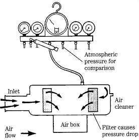
FIG. 11 Stationary and marine technicians sometimes used a manometer-a U-shaped
tube, partially filled with water, with one leg open to the atmosphere and
calibrated in quarter-inch increments-to measure the pressure drop across the
filter. Field mechanics prefer the convenience of a vacuum gauge. The Ford
gauge is calibrated in inch/H2O.
 FIG. 12 Gas flow through a Detroit Diesel turbocharger.
Positive crankcase ventilation (PCV)
Positive crankcase ventilation valves require routine replacement, since cleaning is rarely effective. The 2.2-L Isuzu used in several GM vehicles demonstrates how complex these systems can become. The liquid component of blowby gases is filtered out and collected in a holding tank for return to the crankcase. A check valve under the tank isolates the sump from PCV vacuum. If this valve clogs, the oil level rises in the tank and is pulled over into the intake manifold to produce clouds of blue smoke.
Exhaust gas recirculation
Failure of the exhaust gas recirculation (EGR) valve or control circuitry flags trouble codes, increases smoke levels dramatically and costs power. When used with EMS, the EGR valve incorporates a position sensor and an actuator that can be cycled with the appropriate scanner.
Turbocharger
What follows is a quick rundown on some of the more frequently encountered turbo faults. See Section 9 for more information about these complex machines.
Turbocharger failure has a number of causes, most of them associated with the demands put on the lubrication system by these devices that, in their most modern form attain as much as 400,000 rpm under peak load ( FIG. 12). Momentary interruptions in the oil supply, which might occur during initial startup after an oil change or during sudden acceleration immediately after a cold start, destroys the bearings. If the engine is run hard and abruptly shut down, oil trapped in the turbocharger case absorbs heat from the turbine and carburizes into an abrasive. Many EM systems can be programmed to eliminate cold, wide-open-throttle starts and hot shutdowns.
Other problems include carbon and scale accumulations on the wheels, exhaust side leaks (caused by thermal expansion of the piping), pressure-side leaks (often at the manifold-to-block gasket), and blade-tip erosion. A faulty air filter will "dust" the compressor wheel, giving it a satiny appearance.
Some malfunctions-noise, excessive bearing clearances, cracked exhaust plumbing-obviously involve the turbocharger. A fall off in power, sooty exhaust, low or erratic turbo boost may have causes outside of the unit. Before assuming that the turbocharger is a fault, check the fuel system with particular attention to the injectors, and verify that the pressure drop across the air filter element is within specification. Carefully inspect the turbocharger oil and vacuum lines. And, of course, you need to retrieve the trouble codes. Many EMS blowers incorporate variable geometry, so that boost comes on early during the rpm curve. Malfunctions will flag trouble codes associated with abnormal levels of boost and actuator failure.
Start the engine and listen to the sound the turbocharger makes. With a little practice you will be able to distinguish the shrill sound of air escaping between the compressor and engine and the sound of exhaust leaks, which are pitched at a lower register. If the sound changes in intensity, check for a clogged filer, loose sound deadening material in the intake duct, and dirt/carbon accumulations on the compressor wheel and housing. A stethoscope will amplify any mechanical noise.
Glow plugs
Slow cold starts and persistent white smoke can be caused by failure of one or more glow plugs on indirect injection (IDI) engines. Test individual plugs with the ignition off and a low-voltage ohmmeter connected between the plug terminal and a good engine ground. Most draw about 2 ohm hot, and nearly 0 ohm cold. If the heating element is open, resistance will be infinite.
An open supply circuit denies power to all glow plugs and makes cold starting virtually impossible. Check for blown fusible links verify that the relay, often a solid state device with an internal resistance that drops glow-plug voltage to 6V, is functional. EMS glow-plug controllers vary plug on-time with ambient and coolant temperatures. See Section 11 for details.
Exhaust backpressure
Excessive backpressure can prevent starting, cost power, increase exhaust temperature, and color the exhaust. Water locks-exhaust pipe risers to block water entry on marine installations-should not be used with turbocharged engines.
Look for damaged mufflers and flattened, crimped, or improperly sized exhaust piping. Trouble codes should be flagged if the EMS senses a clogged particulate trap or catalytic converter.
If excessive backpressure is suspected and the source is not obvious, drill and tap a 11/32 in. hole on a straight section of exhaust piping 6-12 in. downstream of the turbocharger. Tap threads for a 1/8 in. pipe fitting. Connect a manometer and, with coolant temperature normal, apply the maximum possible load to the engine. While backpressure varies with the installation, readings higher than 3 in./Hg are cause for concern.
Engine mechanical
Engine malfunctions fall into four categories: fluid leaks, excessive oil consumption, loss of compression, and bearing wear.
Fuel leaks
External fuel leaks are discussed earlier in this section. Fuel contamination of the lube oil (as from failure of Roosa pump seals or HEUI injector o-rings) can be detected by the loss of viscosity and the telltale odor.
Oil leaks
In rough order of frequency, the most common sites of oil leaks are
• Valve cover gasket
• Oil pan gasket
• Timing case gasket
• Front and rear crankshaft seals
• Oil cooler
• Camshaft and oil gallery plugs
Tracing the source of a small leak can be difficult, because oil tends to migrate down and back, toward the rear of the engine. A black light detector or the aerosol powders sold for this purpose help, but the ultimate tactic is to pressurize the crankcase. Connect a low-pressure (5-psi maximum) air line to the dipstick tube.
Soap the engine down and look for bubbles. Light foaming at valve cover gaskets is permissible. The rope-type crankshaft seals used in older engines might leak air and still function when the engine runs; lip seals may foam, but should not hemorrhage.
Internal oil leaks past bearings shows up as a loss of pressure, a condition that should be verified with an accurate test gauge made up to the main oil gallery ( FIG. 13). A pressure drop when loads are applied to a warm engine indicates excessive bearing clearances.
Oil enters the coolant by way of leaks in oil cooler or, more rarely, head gasket. Pressure test the cooler as described in Section 8, "Lubrication systems"; the head must be removed to detect leaks across the gasket, which makes the exercise a bit redundant.
The lower, external oil seal on HEUI injectors is all that stands between high pressure lube oil and the fuel supply. A leak here can empty the sump within a few miles of driving. See Section 6 for more information.
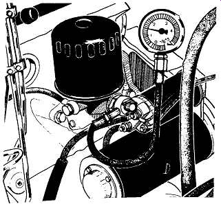
FIG. 13 Verify low oil pressure with an accurate gauge connected to a test
port on the main gallery, as shown here on a Peugeot engine.
Coolant leaks
External leaks are usually visible; identifying internal coolant leak paths requires some detective work. Massive leaks into the combustion chamber produce white smoke at normal engine temperatures. Such leaks can sometimes be seen as coolant flow through the EGR valve.
A burst of steam when the dipstick is touched to a hot exhaust manifold signals the presence of water in the sump. Ethylene glycol coats the stick with brown varnish almost impossible to wipe off. Have the oil tested and, if the test shows the presence of antifreeze, prepare to tear the engine down for cleaning. Large accumulations of coolant in the sump convert the oil to a white, mayonnaise-like emulsion.
Excessive oil consumption
Blue smoke is the primary indicator of oil burning, although catalytic converters can disguise the condition. The question facing the mechanic is the source of the oil.
Blue smoke at all speeds, hot or cold, points to cylinder/ring wear, which can be verified with tests described below. Smoke during acceleration after periods of idle and immediately upon startup indicates leaking valve seals. Oil in the intake manifold and/or air boxes originates from an upstream source, usually leaking turbo or blower seals. But other possibilities should not be overlooked. Sometimes merely changing the air filter element corrects the problem.
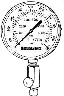
FIG. 14 Ford-supplied cylinder compression gauge.
Loss of compression
Disabling one injector at a time will isolate any weak cylinders. If changing out the associated injectors does not restore power, the problem is almost surely compression-related. Loss of compression across all cylinders will be accompanied by high oil consumption and a noticeable reduction in power output.
The cylinder compression gauge ( FIG. 14) is an essential tool for diesel mechanics. Test procedures vary with make (e.g., some manufacturers specify a cold reading, while others require that the engine be at normal operating temperature).
But the general procedure is as follows:
1. Cut off the fuel supply or disconnect the camshaft position sensor on computerized engines. Otherwise, the cylinder under test can fire and destroy the gauge.
2. Disable all cylinders by (depending upon how the gauge is mounted) removing the glow plugs or injectors.
3. Test each cylinder in turn, allowing about six compression strokes per gauge reading.
4. Check the readings against published specifications and against each other.
Variations of 20% or more between cylinders results in noticeable roughness.
WARNING: don’t squirt oil into the cylinder in an attempt to determine if the compression loss is due to rings or valves. The cylinder might fire.
FIG. 15 illustrates a GM leakdown test kit with glow-plug adapter. Unlike competitive testers, the unit does not measure leakdown percentage, but it does indicate the source of air leaks, which is the purpose of the exercise.
1. Remove the radiator cap and warm the engine to operating temperature.
2. Shut off the engine and, using the timing marks, position No. 1 cylinder at top dead center (tdc). Finding tdc for the remaining cylinders is a bit challenging, but can be accomplished with a degree wheel or with the help of the whistle supplied with the kit.

FIG. 15 GM cylinder leakdown tester includes air-line adapters, regulator,
gauge, and top dead center (tdc) whistle. The whistle sounds as the piston
nears tdc on the compression stroke.

FIG. 16 Potential leak sites for compression.
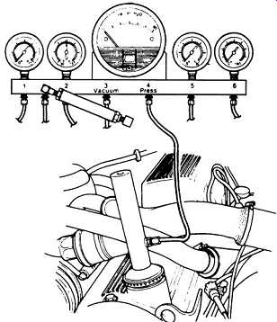
FIG. 17 A crankcase pressure tester is part of the Ford PN 0190002 gauge
bar set.
WARNING: if a piston is not at or very close to tdc, the engine will "motor," catching a hapless mechanic in the fan or belts.
3. Install the tester and apply about 75 psi of compressed air to it.
4. The significance of the various leak sites is listed in FIG. 16.
The amount of blowby past the rings is a rough indicator of cylinder bore/ring wear. FIG. 17 illustrates the test apparatus, consisting of a pressure gauge and an adaptor that replaces the oil filler cap. PCV atmospheric vents must be sealed.
A major limitation of this test is that few manufacturers provide rpm/blowby pres sure specifications. The mechanic must establish the norm while the engine is still healthy.
Oil analysis
Short of tearing the engine down for inspection, oil analysis is the best index of wear. The technology, developed initially for diesel locomotives and perfected by the U.S. Navy, can predict engine failure with some exactitude. The oil sample undergoes spectroscopic analysis to identify 16 or more elements with an accuracy of within one part per million. Bearing wear shows up as lead, silver, tin, and aluminum; liner and ring wear as iron and chromium; valve wear as nickel; and bushings as copper. Silicon and aluminum particles suggest air filter failure.
Prev. | Next
Home top
of page Similar articles