Injectors
Mechanical injectors consist of two main parts-an injector body, or nozzle holder, and a needle ( FIG. 21). The injector body secures the assembly to the cylinder head, and includes connections for fuel inlet and return lines.

FIG. 21 Cross-section and exploded view of two CAV injectors. GM Bedford Diesel
and Lehman Ford Diesel.
A spring-loaded needle ("nozzle valve") in the drawing, controls fuel flow through the injector. At NOP fuel pressure exerts sufficient force on the raised shoulder near the tip of the needle to overcome spring tension. The needle retracts clear of the orifice and injection commences. Once the needle lifts, its full cross-sectional area-the shoulder and tip-comes under fuel pressure. Consequently, less pressure is required to hold the needle open than to unseat it. This feature holds the nozzle open as fuel pressure drops in response to injection. When the pump plunger descends and the delivery valve closes, fuel pressure drops abruptly. The return spring forces the needle down to seal the orifice and injection ceases.
The smaller the nozzle orifice, the finer the fuel spray and, all things equal, the less ignition lag. But if too small, the orifice limits engine output by restricting fuel flow. Multi-hole nozzles, some with a dozen or more, electrically discharge, machined orifices that satisfy both flow rate and atomization requirements, have become standard on DI engines.
IDI engines employ pintle nozzles, two varieties of which are illustrated in FIG. 22.
The pintle is an extension of the needle that, when retracted, produces a hollow, cone shaped spray. Because of the large diameter of the orifice and the shuttle action of the pintle, these nozzles are less susceptible to carbon buildup than multi-hole types.
The throttling pintle introduces fuel in a staged sequence to reduce the sudden rise in pressure and heat during initial combustion. The pintle has a reduced diameter on the tip that, when seated, extends into the combustion chamber. Yanmar and most other manufacturers use a throttling pintle with the tip in the form of an inverted cone, shown on the right in FIG. 22. During the initial phase of injection, the cone lifts so that its base almost fills the orifice. At full lift the cone retracts clear of the orifice for maximum fuel delivery.

FIG. 22 Pintle (left) and throttling pintle nozzles. Yanmar Diesel

FIG. 23 Ford-supplied injector tester. These tools have multiple uses, including
testing common-rail fuel manifolds and HEUI oil galleries for leaks.
Injector service
Regardless of the nozzle type, injectors should:
• Discharge cleanly without "after-dribble," which tends to collect in the cylinder between cycles.
• Atomize fuel for rapid combustion.
• Direct the spray into the far reaches of the cylinder, but without impinging against the piston or chamber walls.
Most malfunctions are caused by carbon buildup on the tip, which distorts the spray pattern and can sometimes stick the needle or pintle in the open position.
Automatic injectors can be tested with the apparatus shown in FIG. 23. Similar tests can be performed on unit injectors by loading the pump cavity with fuel and applying force to the pump plunger.
WARNING: Wear eye protection and heavy gloves when testing injectors. Fuel spray can cause blindness and blood poisoning.
There are four standard tests-spray pattern, NOP, sealing effectiveness, and chatter.
Spray pattern
Connect the tester as shown and, operating the pump lever in short, rapid strokes, observe the spray pattern. Pintle nozzles should produce a finely divided spray of uniform consistency and penetration ( FIG. 24). Multi-hole nozzles generate a wide, fan-like pattern ( FIG. 25). It can be helpful to direct the discharge against a piece of paper and compare the pattern to one produced by a new injector.
Nozzle opening pressure
Slowly depress the pump lever and note the peak gauge reading. Compare this pressure with the manufacturer's NOP specification. Some specifications are fairly broad, and engines may not idle properly unless NOPs cluster at one or the other end of the specification range. Most needle-return springs can be stiffened with shims.
Sealing
Dribble standards have become tighter in recent years. The pintle injector illustrated in FIG. 26 should remain fuel tight under 80% of NOP for at least 10 seconds.
Note and correct any other source of leakage.
Chatter:
Injector opening is normally accompanied by a sharp "pop," which suggests that the needle retracts cleanly. Verify this action as the pump lever is cycled rapidly.
However, leaking injectors can be made to chatter and some perfectly good throttling pintle injectors pop open, but refuse to chatter, no matter how adroitly the pump handle is worked.

FIG. 24 Spray pattern diagnosis-modified pintle nozzle, IDI engines.
Timers:
Moving fuel through an open injector requires time and, once injected, additional time is needed for the fuel to ignite. As engine speeds increase, less time is available to accommodate these delays, and the start of injection must occur earlier.
The drawing back at FIG. 10 shows the VE hydraulic timer in cross-section.
Pressure developed by the feed pump rises in an almost linear fashion with engine speed. As pressure increases, the piston moves to the right, compressing its return spring. A roller transfers this motion to the drive cam, turning it few degrees against direction of shaft rotation.
Mechanical timers are similar to SI advance mechanisms, in that they employ centrifugal weights to sense engine speed and advance the cam (FIG. 27).
Spring tension on the weights determines the cut-in speed and shims fix the travel limit.
To check timer operation, connect a timing light to an injector pipe and run the engine up to speed. Injection should advance smoothly without hesitation as the rack is extended. Specifications vary, but most applications require 5-7.5_ of total advance.

FIG. 25 Spray pattern diagnosis-multi-hole nozzle, DI engines.
Diaphragm controls
Injector pumps often include a diaphragm-operated control that reduces fuel delivery at high altitudes and/or increases fuel at wide throttle angles for turbocharged applications. Diaphragms are tested with a vacuum gauge.

FIG. 26 Dribble test-pintle nozzle, IDI engines.
Centrifugal governors
Spark-ignition engines have a built-in governor in the form of a throttle valve that, even wide open, limits the amount of air passing into the engine. Diesels have no such limitation, since surplus air is always available for combustion. Engine speed depends solely upon the amount of fuel delivered. If the same volume of fuel necessary to cope with severe loads were delivered under no-load conditions, the engine would rev itself to destruction. Consequently, all diesel engines need some sort of speed-limiting governor.
Most governors also control idle speed, a task that verges on the impossible for human operators. This is because the miniscule amount of fuel injected during idle exaggerates the effects of rack movement. Automotive applications are particularly critical in this regard. Idle speed must be adjusted for sudden loads, as when the air conditioner compressor cycles on and off, and when the driver turns the wheel and engages the power-steering pump. In addition to limiting no-load speed and regulating idle speed, many governors function over the whole rpm band. The operator sets the throttle to the desired speed and the governor adjusts fuel delivery to maintain that speed under load. The degree of speed stability varies with the application. No governor acts instantaneously-the engine slows under load before the governor can react. Course regulation holds speed changes to about 5% over and under the desired rpm, and is adequate for most applications. Fine regulation, of the kind demanded by AC generators, cuts the speed variation by half or less.
Centrifugal governors sense engine speed with flyweights and throttle position with spring tension. FIG. 28 illustrates the principle: As engine speed increases, the spinning flyweights open to reduce fuel delivery. As the throttle is opened, the spring applies a restraining force on the flyweight mechanism to raise engine speed.
So much for theory. In practice, centrifugal governors demonstrate a level of mechanical complexity that seems almost bizarre, in this era of digital electronics.
But millions of these governors are in use and some discussion of repair seems appropriate.

FIG. 27 Centrifugal fuel timer varies injection timing in response to changes
in engine speed.
Service
Governor malfunctions-hunting, sticking, refusal to hold adjustments-can usually be traced to binding pivots. In some cases, removing the cover and giving the internal parts a thorough cleaning is all that's necessary. If more work is needed, the governor and pump should be put into the hands of a specialist.
To appreciate why this is so, consider the matter of bushing replacement, which seems like a simple enough job. Using the CAV unit as a model, the critical bushings are those at the flywheel pivots (225 in FIG. 29) and the sliding bushing (231) on the governor sleeve. To remove and install the flyweights you will need CAV special tool 7044-8. Bushing press in, but factory reamers are needed to size them properly.
And a governor with enough hours on it to wear out bushings will almost surely need recalibration, which can only be accomplished with a factory tooling that correlates piston stroke with rack position.

FIG. 28 Bosch-type centrifugal governor. The flyweights react against throttle-spring
tension to set the speed of the engine. As loads are encountered, the engine
slows, the flyweights exert less force, and the spring extends the rack to
restore engine rpm. Yanmar Diesel Engine Co., Ltd.
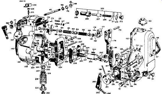
FIG. 29 CAV governor in exploded view.
Pneumatic governors
Pneumatic, or flap valve, governors are less expensive than centrifugal governors and more amenable to repair. The velocity of air moving through the intake manifold is a function of piston speed. The faster the engine runs, the greater the velocity. Pneumatic governors sense this velocity as vacuum developed by a venturi mounted on the air intake.
The venturi restricts the flow of air and, so doing, reduces its pressure. This relation ship has a constant of 20, as shown in FIG. 30. If we use consistent terms and multiply pressure times velocity at any point in the venturi, the answer is always 20, or something approximating that number. Nor need the venturi be the sort of streamlined restriction shown in the drawing; any impediment accelerates air flow and reduces its pressure.
Pneumatic governors, while by no means the state of the art, are still encountered on marine and industrial engines. The example discussed below is one of the most complex.

FIG. 30 The venturi constant.
MZ
This unit, shown in cross-section in FIG. 31, uses a flap, or butterfly, valve (4) as a variable venturi. A tube bleeds vacuum from the edge of the valve to the left or low pressure side of the diaphragm housing. A second tube brings filtered air at atmospheric pressure to the right side of the housing. The spring-loaded diaphragm (8) separates these two halves of the housing and connects to the fuel rack.
The flap valve is free to pivot in response to incoming air velocity. At low engine speeds the valve positions itself as shown in the drawing. All air entering the engine must accelerate and squeeze past the obstruction created by the edge of the valve and the vacuum-line connection. The diaphragm responds to the resulting depression by moving toward the left, or low-pressure, side of the housing. Fuel delivery is reduced.
If the engine decelerates as when encountering a load, vacuum drops and the diaphragm shifts toward the right to increase fuel flow.

FIG. 31 MZ centrifugal governor.
At wide-open throttle, the velocity of incoming air pivots the flap valve full open.
Sensing the low level of vacuum, the diaphragm shifts to the right, extending the rack.
The governor also includes the mechanism shown in FIG. 32 that reduces fuel delivery at idle. As the diaphragm moves to its extreme leftward position, it brings the stop lever (6) to bear against the stop bolt (5). This action compresses the balance spring (11) and displaces the rack (7) toward the no-fuel position. As engine speed increases, the diaphragm moves to the right. The balance spring mechanism moves with it, away from the stop lever. Once clear of the lever, the spring has nothing to react against and is out of the circuit.
Service:
The leather diaphragm should hold 500 mm/H2O of vacuum with a leak-down rate of no more than 2 mm/sec. It should be flexible enough to collapse of its own weight when held by the rim. Nissan dealers can supply the special diaphragm oil required to soften the leather.
A screw under the circular end cover reacts with the auxiliary idle spring (3) to set the idle speed. Tightening the screw moves the rack to the right to increase fuel delivery and idle rpm. But the effect extends to all engine speeds ( FIG. 33). Fuel delivery for best idle over-fuels the engine at high speed and, conversely, a setting that gives best fuel economy at speed, costs low-end power. The adjustment is a compromise.
Other adjustments require a test fixture available to dealer mechanics. For example, the stroke adjustment, shown at 4 in FIG. 32, is made to factory specifications with the diaphragm chamber evacuated and the pump turning 500 rpm. To further complicate matters, balance-spring adjustment must be done by comparing its action with a known good unit.

FIG. 32 MZ balance mechanism.
Unit injection
Thus far, we have discussed three types of mechanical fuel systems: air blast, early common-rail, and jerk pump. The last of these systems, and in some ways the most attractive, is unit injection.
Unit injection combines the pumping function with injection. That is, each UI incorporates its own high-pressure pump driven from the engine camshaft. Injection pressures, often in excess of 20,000 psi, are confined entirely within the injector bodies. The lines that connect the lift pump with the injectors see only moderate pressures, on the order of 50 psi. Consequently, UI systems are virtually leak-proof.
Mechanics, at least the ones old enough to remember first-generation Volkswagens and Detroit Diesel two-strokes, like the way UIs localize problems. When a UI fails, only the associated cylinder goes out. And because an engine will run with one or two bad injectors, it becomes its own test stand.
FIG. 34 illustrates the standard Detroit Diesel fueling circuit. The restrictor draws off a portion of the incoming fuel to cool the injectors before returning to the tank. Two stages of filtering are provided, with the primary filter on the suction side of the fuel pump.

FIG. 33 MZ injection curves.

FIG. 34 Unit injectors combine a high-pressure pump and injector nozzle in
the same assembly. Detroit Diesel

FIG. 35 Cutaway of a Detroit unit injector.
In addition to the parts found on more conventional injectors, a UI has a mushroom shaped cam follower, return spring, pump plunger, fuel-supply chamber, and one or more check valves ( FIG. 35). The rack controls fuel delivery by rotating the plunger as described under "Inline pumps." Fuel enters the injector and passes to the supply chamber. As the engine cam forces the plunger down, fuel trapped in the supply chamber comes under increasing pressure. At NOP, the needle valve lifts and injection begins. The disc-shaped check valve is fail-safe. Should needle fail to seat, the check valve closes to prevent air from entering the fuel supply.
Other than changing out plunger-related parts, unit injectors are not normally considered field-repairable.
Low-pressure system:
Regardless of the type of high-pressure system, all engines employ similar low pressure systems.
Lift pumps:
A fuel supply, feed, transfer, or lift (the terms are interchangeable) pump sup plies low-pressure fuel to the suction side of the injector pump or unit injectors. Most lift pumps are driven mechanically, although in recent years, electric drive has become popular. Pressure varies with 50 psi as a ballpark figure.
Stanadyne, Lucas/CAV and Bosch distributor-type injector pumps employ an integral vane-type lift pump as pictured back in FIG. 9 and subsequent drawings. The sliding vanes rotate in an eccentric housing with the outlet port on the periphery.
Gear-type lift pumps, similar to lube-oil pumps, develop pressure from the tooth mesh and usually incorporate a spring-loaded pressure-limiting valve.
Chrysler-Nissan SD22 and SD33 engines feed through a piston pump driven off the injector pump ( FIG. 36). The operation of the pump is slightly unorthodox, in that fuel is present on both sides of the piston to eliminate air locks. As the piston retracts, fuel under it’s expelled and the inlet check valve opens to admit fuel into the chamber above the piston ( FIG. 37). As the piston rises, the check valve closes to permit the upper chamber to be pressurized. Fuel under the piston then reverses course to fill the void left by the rising piston. Near tdc the spring-loaded discharge side valve opens. Spring tension determines pump pressure. The upper chamber can also be pressurized manually to bleed the system.
Small engines are often fitted with low-pressure diaphragm pumps such as the AC unit pictured in FIG. 38. The pump consists of a spring-loaded diaphragm activated by the engine camshaft. Inlet- and discharge-side check valves are often interchangeable.
Lift-pump service:
Loss of pressure is the definitive symptom of pump failure, although it would be helpful if manufacturers provided output volume specifications. Before condemning the pump, check for air leaks as described in the previous section. A length of transparent plastic tubing spiced into the pump output line will reveal the presence of air bubbles.
Pump vanes wear in normal service and can stick in their grooves when the fuel turns resinous after an extended shutdown. Gear-type pumps should require no routine maintenance other than inspection during the course of engine overhaul. Wear tends to localize on the pump cover. When pump failure, as from a sheared drive gear, is suspected, it’s sometimes possible to establish that the gears turn by inserting a fine wire into the outlet and cranking the engine. The wire should vibrate from contact with the spinning gears.

FIG. 37 Operation of the unit shown in the previous illustration. Marine
Engine Div., Chrysler Corp.

FIG. 36 Piston-type Chrysler-Nissan lift pump.
Check valves are the weak point of reciprocating (piston or diaphragm) pumps.
Most check valves can be removed for cleaning or replacement. When this is not possible, a piece of wire inserted into the fuel entry port should unstick the ball, at least temporarily. Diaphragms should be changed periodically and the housing cleaned every 200 hours or so of operation ( FIG. 39). When installing these pumps, it’s good practice to bar the engine over so the pump lever rides on the lower part of the cam.

FIG. 38 AC diaphragm-type lift pump used on Bedford trucks.

FIG. 39 Lift pump inspection. Ford Industrial Engine and Turbine Operations

FIG. 40 Cartridge-type fuel filter with water separator. GM Bedford Diesel
Fuel filters and water separators
Most engines incorporate three stages of filtration-a screen at the tank and paper-element primary and secondary filters. Filters are rated by the size of particle trapped: a typical installation would employ a 30-micron primary filter and a secondary of between 10 and 2 microns. A water separator is often built into the primary filter ( FIG. 40), which also may include a connection for fuel return and an electric heater to prevent fuel gelling and waxing in cold climates.
When a filter element is changed, entrapped air must be bled as described in Section 4.
Prev. | Next
Home top
of page Similar articles