LAYING UP THE WALLS OF A LOG HOUSE IS essentially a repetitive process. It involves notching, stacking, aligning, sealing, and securing the pieces, while constantly checking plumb and level and either leaving whatever openings are necessary, or notching starter cuts for them. There are two possibilities: stacking the logs horizontally one atop another, or standing them up vertically, side by side. Either concept is simple enough, but the actual work is not, and must be done with care, patience, and good craftsmanship if the results are to be good. In addition, there are a number of details and construction variants that need explaining. You will have to make some decisions at the outset as to just how you want to construct the walls, and those methods will carry through for the entire construction process.
LOG LAY-UP
Logs that have been milled or flatted top and bottom to a uniform thickness and no taper need only be dropped into position, aligned properly, and secured. With some kinds of corner joints, such as a mortise and tenon, each layer of logs is at the same level all the way around the structure—a course, like bricks or blocks in a masonry wall. With other kinds, op posing sets of wall logs are roughly a half- thickness above or below each other; this might be compensated for in the foundation or at the top plate.
When fully round logs—those that have been hewn or sawn flat top and bottom but retain the taper—are used, the situation is different. Then the logs are placed tip on butt around the perimeter of the structure first in one direction, then in the other, in rounds. Assuming tapered sill logs to be the first round, set clock wise, the second round will be set counter clockwise, tip on butt. At this point, the corners will be roughly the same height from the foundation, provided that you have selected logs of comparable diameter and taper. When the third round is set, diagonally opposite corners should be about the same height, but for four corners there will be two different heights—the round will be uneven. The fourth round will even out, and so on. Odd-numbered rounds are uneven, even ones are approximately level. For this reason, it is best to plan for an even number of rounds; this avoids extra work at the top of the wall. When the plate log is placed, the entire top of the wall structure should be in the same plane, otherwise there will be trouble later on in building up a true, squared-up roof.
There are also two ways of setting up the walls. You can use logs of similar diameter all the way up, or you can start with large logs at the bottom and diminish the log diameters successively with each added round. The top log, however, should not be dramatically skinnier than the bottom one. The method you choose is a matter of personal preference. Either way, the trick is to match and fit the logs very care fully, checking plumb and alignment and corner heights all the while, and judging the taper and overall shape of each log as it is added, to best fit each situation. There are no hard and fast rules here, it is largely a matter of common sense, judgment, and a good eye for form and fit.
CORNER CONSTRUCTION
The corners of log houses are constructed in two general ways: extended and flush. In an extended corner the logs pass by the foundation corner point and protrude beyond the side- walls anywhere from 6 inches to several feet, depending upon the decision of the builder. These log protrusions are called wings or end- work, and can be formed in a number of ways, both plain and fancy. In a flush corner design, the logs meet and match right at the corners.
Both of these methods can be used for in side corners, where the log ends are to the in side of the building, or for outside corners where the log ends are exposed on the exterior.
Actually the term is a bit of a misnomer, be cause flush exterior corners should not really be cut off truly flush with the wall surface (though they sometimes are). At least 6 inches of free log should be left, so that the inevitable end-checking of the log and subsequent en trance of moisture will occur outside the structure and not within the corner joints where it can cause damage. Combination corners can also be made, with extended corners on the exterior and flush in the interior—they can be truly flush here—to conserve space and allow a less rustic appearance.
In most types of corners (there are some exceptions) the logs are locked together with joints. There are many that can be used, each with advantages and disadvantages. By and large, the more complex the joint the stronger the construction. However, modern log houses seldom depend entirely on the corner joinery alone for strength; mechanical fasteners are used as well.
Some joints are easier to make than others, and some are more susceptible to water penetration than others. Most can be used with either flatted or round logs, and some with squared logs or beams as well. Whichever one you choose (or two, if you plan to combine both extended and flush corners in the same structure), follow through the entire construction process with them, including the sill logs.
The most critical part of constructing corner joints, and all others in the building, for that matter, lies in the fitting. The cuts must be accurate and well fashioned so that the mating surfaces fit together correctly and snugly like the parts of Chinese puzzle. This is largely a matter of careful and accurate scribing, making clean and exact cuts, patient and precise trimming, and time. Lots of time. Sloppy joints are not only bad workmanship, they weaken the structure and allow excessive moisture penetration and air infiltration.
One further note: If you are not sure just how one or another of these joints will actually look when completed, or if you have never done any log joinery, it’s a good idea to take a few hours and do some practice notching on a few log chunks, or even poles. This will give you an idea of what you like best, how to proceed, and a little experience as well before you start whittling away on the nice sill log.
Butt Corner
The butt corner joint ( Ill. 6-1) is a fairly simple one to make and relatively weatherproof, but lacks strength because neither the logs nor the courses lock together. One log extends to or beyond the corner point, while the other in the same course butts tight against the side of the first. Scribe the butting log to the side of the extended log and cut or cope to exactly the same contour for a tight fit. Drive a pair of spikes through the extended log side and into the butting log end. On the next course up, reverse the pattern so that the extended logs al ternate with butting logs in each respective wall.
Ill. 6-1. A butt joint corner with alternate extended logs.
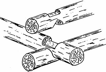
Saddle Notch Corner
The saddle notch corner (Ill. 6-2) is one of the most popular joints because it is effective, sheds moisture well, makes a relatively strong joint (both logs and rounds lock together), and is easy to fashion. This joint can be used only with extended corners.
Ill. 6-2. A saddle notch corner.
The joint is made on the log bottom only, and extends about halfway through the log. It is made by first resting the log on top of the one to which it will be joined, and carefully scribing an outline of the rounded notch to the same contour as the upper surface of the log below ( Ill. 6-3).
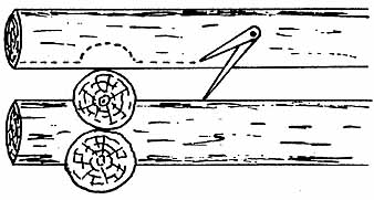
Ill. 6-3. Use dividers to scribe a log for a saddle notch
cutting guideline.
Roll the log over and make a series of saw- cuts straight down in varying depths to almost meet the notchline. Cut the remaining chunks away with a chisel and mallet, and at the same time take the bottom of the cut down to the scribed line ( Ill. 6-4). The interior face of the cut should be dished slightly downward and inward so that it forms a very shallow bowl.
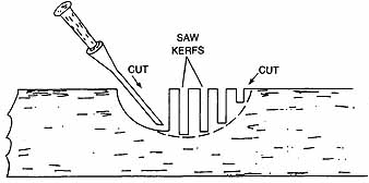
Ill. 6-4. Cutting a saddle notch.
Then the final shaping is done so that the fit is exact. Final settling can be done by running a small coping saw around the thin edge of the notch as the log rests in place; when the cut is finished, the log will set down tight. The joint is usually secured with one spike driven down through the center of the upper log.
Ill. 6-5. A double-round notch corner.
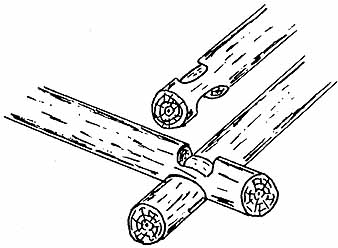
Double-Round Notch Corner
The double-round notch corner ( Ill. 6-5) is a more difficult construction, but it is also somewhat stronger than the saddle notch because of the double locking. It has one drawback in that moisture can seep down into the upper notch.
Make the notches in both top and bottom of each log, extending about a quarter to a third of the way through in each direction, so that the joined logs lock together completely. The bottom notch is rounded inward just as the saddle notch is. The upper notch must be rounded upward in the same conformation as the lower notch of the log above. This requires a considerable amount of shaping, but can be done with chisel and mallet, a small drawknife, and/or a spokeshave. If the logs are relatively uniform in size, a template can be made up to aid in cutting snug-fitting and uniform notches. This is an extended corner construction.
A-and-V Joint Corner
The A-and-V joint ( Ill. 6-6) is a simple double-locking joint to make with a few quick saw cuts and a bit of chisel work. The cuts are flat- bottomed, and only a small amount of contouring is needed at the sides of the upper notch. The A-cut is made in the top of the log, with the V-cut directly below. Size of the cuts is determined by the size of the logs, and calculated so that when the joint faces come together there will be no gap between the mating logs. A single spike through the center of the joint is sufficient to lock each log solidly in place. Water-shedding capabilities are good. This joint is particularly useful with small logs, be cause it can be made so that a minimum of material is removed and the strength of the log is not seriously impaired. This construction is used only with extended corners.
Ill. 6-6. An A-and-V joint corner.
Tenon Joint Corner
The tenon joint corner ( Ill. 6-7) is also an easy double-locking joint to make, and is used only for extended corners. The first step is to flat the log on all four sides in the immediate joint area; this can be done with an axe, adze, or hatchet. With like-size beam sections to work with, you can then fashion the tenons by making several parallel saw cuts, and chip away the excess wood with a chisel to make a flat-bottomed, square-sided cut. This is a strong and tight joint that locks well and is reasonably weathertight. A single spike will tie the joint on small logs, and two slightly angled ones will serve for large ones.
Ill. 6-7. A tenon joint corner.
Dovetail Joint Corner
The dovetail joint corner ( Ill. 6-8) is used in flush corner constructions and is one of the more difficult to make. The log ends are subject to checking and opening over time right at the joints, which is a drawback, but it is a strong locking joint of classic appearance.
Ill. 6-8. A dovetail joint corner.
The log ends must be squared first, which can be done by cutting a few inches of the log end into a beam; the cut faces must be at right angles to the beam surfaces. Then each end is fashioned by cutting and chiseling into dove tail keys and slots. There are two variations: the common dovetail where the cuts are squared on one joint face and angled on the other, and the compound dovetail where the joint lines are angled on both faces. Either way, careful cut ting and fitting is necessary to get the joints to fit together snugly while at the same time keeping a tight mating fit along the lengths of the logs. The common dovetail is held together with one spike down through the center of the joint. The compound dovetail totally interlocks, though, and if the joint is well made, spiking is superfluous. Both joints are best suited to fairly large log diameters that allow plenty of material to work with.
V-Joint Corner
The V-joint corner ( Ill. 6-9) is another system whereby one log extends and the other joins it, in alternating courses. The butting log is shaped in a sharp V, with a matching V-notch cut into the passing log. This is a fairly strong joint when properly joined with two spikes through the passing log and into the end of the butting log, and a third spike toe-nailed down from the top into the angle of the V. Note, how ever, that as with the butt joint corner, the successive courses of logs do not interlock with one another.
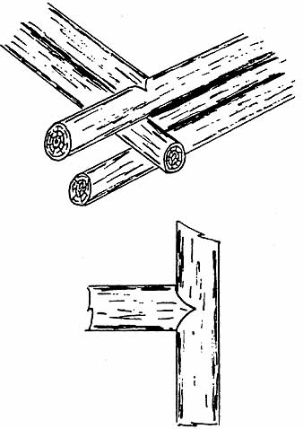
Ill. 6-9. A V-joint corner.
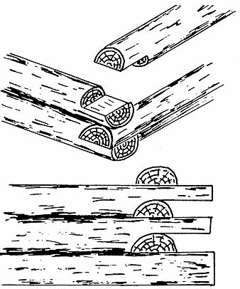
Half-Cut Joint Corner
The half-cut or half-lap joint corner ( Ill. 6-10) is one of the easiest joints of all to make, and probably the least satisfactory. It is not a strong joint because neither the joining logs not the courses interlock at all. Both the joining logs and the courses must be spiked together or otherwise secured to hold them in place. This joint also does a poor job of shedding moisture, and can even trap it to the extent of funneling it inside the structure. Even so, it is sometimes used because of its simplicity. The joint is made by merely sawing halfway through the top of one log and the bottom of the next and splitting the half-sections away.
Ill. 6-10. A half-cut joint corner.
Ill. 6-11. A saddle-end joint corner.
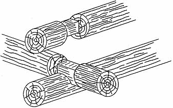
Saddle-End joint Corner
The saddle-end joint corner ( Ill. 6-11) is nearly as easy to make as a half-cut joint corner but is more effective. The joint is made by shaping an inward-curving cut on the bottom of the log and then splitting away the entire end half. For best results the curved portion of the cut should be contoured to the log which it will join, by scribing, coping, and fitting it snugly. This joint can be used for either flush or ex tended corners, and sheds moisture well. Each joint should be secured with a pair of spikes driven down from the top at opposing angles.
Full Post Corner
Installation of a full corner post ( Ill. 6-12) makes a neat and clean corner construction suitable for either inside or outside corners. The corner post should be carefully selected to be straight and true and of as uniform diameter as possible.
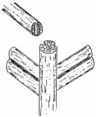
Ill. 6-12. Full corner post construction.
Cut two wide grooves or dados the full length of the log and at 90 degrees to one another. Stand the log up on the foundation corner, secure it in position with a pair of long pins bedded in the foundation for that purpose, and solidly braced plumb. Square the log ends off, and cut vertical tenons matching the post dado width on them.
The cut log face can be left at right angles to the tenon faces, but a much better and more attractive joint can be made by setting the log in place, scribing the post contour, and coping the joint to fit snugly. Mate each successive log along its length to the log below, as necessary. Set the log with the tenon fully home in the dado and make the final fitting. Spike the logs to one another; they can be se cured to the post by driving one spike through and into the tenon, but only if the tenon is wide and unlikely to split. The post is held in place at top and bottom. Properly constructed, this makes a reasonably strong corner, and if well caulked and sealed it is also quite weatherproof.
Quarter-Post Corner
Though easily made and attractive, the quarter- post corner ( Ill. 6-13) is less satisfactory from several standpoints. The construction is not very strong and is held together only by a lot of spikes. Shrinkage can cause joint separation, which in turn can cause problems. The method of spiking also mean’s that the logs cannot settle as they shrink in diameter, so the horizontal joints are likely to open up as well unless the logs are exceptionally well-seasoned. In this construction the logs are laid and squared at the ends, mating with the inserted quarter- round post. Heavy bracing is needed for both the post and the walls as the walls are laid up. The cuts are simple and this method is suitable for either inside or outside corners, but is best confined to small structures.
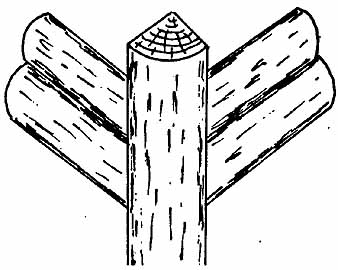
Ill. 6-13. Quarter-post corner construction.
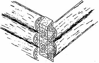
Plank Corner
Plank corner construction ( Ill. 6-14) is a variation upon the above. The corner is both stronger and more weathertight and the possibilities for shrinkage opening up the vertical joints is alleviated to some degree. However, because the logs are securely spiked to the corner planks, there is no way they can settle properly. Unless the wood is exceptionally dry to begin with, the horizontal joints between the logs are likely to open up from shrinking. Construction is accomplished by inserting a right- angled pair of nominal 2-inch dimension stock of appropriate width into the valley between the log ends. Mortise these planks full thick into the log ends, leaving an exterior overlap of log facing, and spike to the log ends. Then spike a quarter-round log into place to hide the dimension stock and fill the corner.
Ill. 6-14. Plank corner construction.
Ill. 6-15. The most common endwork configurations.
END WORK
Endwork or “wings” are the general terms for the treatment given to the log ends of walls, whether interior or exterior. If the logs are cut off flush or are all butted at the corners, there are no wings, just ordinary squared corners. But where the corners are made with logs ex tended in butt-and-pass or pass-and-pass con figurations, this is endwork. Often as not the arrangement is very simple and almost automatic—as the logs are laid up, the ends are left to project somewhat beyond the wall lines and are merely cut off even from top to bottom. At least 6 inches of log should be left, and the choice is often about 12 inches or so. If the logs are laid butt-and-pass, this results in the familiar staggered pattern; if pass-and-pass, the result is a short wall extension ( Ill. 6-15).

Ill. 6-16. Extended upper and lower logs can frame a privacy
screen or a grille type of endwork.
There is also an opportunity here for more artistic renderings. For example, by extending one or two logs at the top and bottom of a wall for several feet, you can then frame in between them and create a privacy screen; an extension of several logs top and bottom could include a grille ( Ill. 6-16). The wall logs can also be extended at the corners for predetermined approximate lengths during construction, then cut to any of various patterns after completion.
There are numerous possibilities, such as angel-wing, parabolic, butterfly, and buttress endwork; some of these are shown in Ill. 6-17. Though this kind of endwork is most effective when the logs are laid up in rounds and each log end passes the corner, it can also be done with alternate passing logs.
Ill. 6-17. These are a few of the various patterns that
might be employed in endwork.
SPLICING LOGS
Except in the smallest of log structures, a certain amount of log splicing is practically impossible to avoid. It is a good idea, though, to keep the number of splices as low as possible, because each one tends to weaken the overall structure by a small amount. Splices should al ways be well staggered so that they never lie above one another anywhere in the same wall. Try to avoid splicing more than once in a single continuous run of log, because two or three splices can seriously diminish the strength of that course, and detract from the appearance. Also, splices should be made well away from window or door openings, well out into a span of wall. When making splices, match the log ends to be spliced as closely as possible in diameter and general configuration, and try to maintain similar tapers in the two pieces. Some trimming with plane or spokeshave can be done around the splice after it has been put together to make the two logs meld well.
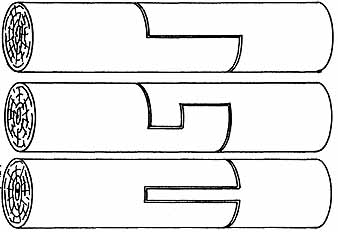
Ill. 6-18. A half-lap log splice.
Ill. 6-19. A squared log splice.
Ill. 6-20. A tongue log splice.
There are several methods of making a splice joint. The simplest is called the half-lap ( Ill. 6-18). Make the lap at least a foot long, and more if you can. Spike or bolt the splice solidly together. You could also use the squared splice ( Ill. 6-19), which is more difficult to make but is also a good deal stronger. This joint requires accurate measurements and clean, precise cuts in order to fit together properly. Make the laps as long as you can and spike or bolt the two ends securely together. Yet another possibility is the tongue splice ( Ill. 6-20), which is a form of mortise and tenon. The log ends are squared, and a long tongue or tenon is cut on one log end with a matching slot or mortise cut in the other. The two are then slipped together and spiked or bolted.
The last method is the spline splice, one commonly used by log house kit manufacturers. This entails first squaring the log ends so that they match. Cut matching mortises or dados into the log ends, positioned so that they will be vertical when the log is set in place. The width and depth of this groove is not a crucial matter, so long as it is substantial. Drive a tight- fitting wood (or sometimes rigid insulation) spline into the dados, locking the logs together and sealing the joint ( Ill. 6-21). Spikes or nails are not used here, because the logs are other wise secured solidly in place. The spline itself strengthens the joint, keeps the logs aligned, and provides a weather seal.
Ill. 6-21. A spline log splice.
JOINING LOGS
Joining the logs together where they bear upon one another along their length must be done just as carefully as building up the corners. If properly fitted, these joints make for a stronger and tighter house; conversely, if they are sloppily done, problems are sure to arise later on. The joints provide additional stability and strength to the log structure, while helping to keep the logs properly aligned as they shrink, settle, and try to warp or twist. Tight, firm joints, especially those with plenty of bearing surface between the log faces, afford much greater stability and a tighter weather seal than do poorly made joints. The better the joints are made and fitted, the more easily they can be sealed off to provide a snug and thermally efficient building, and the better the sealing will stand up over the years. And because better joining means better and more effective sealing, there is less opportunity for moisture to work its way under the seals and into the joints as the seals begin to sluff away or deteriorate. Paying close attention to the proper joining and sealing of all the logs at the outset, even though this increases construction time, pays big dividends and reduces difficulties over the long haul.
The simplest log construction uses no lengthwise joints whatsoever, and obviously is the least effective construction as far as strength, stability, and weather-tightness is concerned. It is also the most difficult to seal. The logs are just stacked one atop another with the corner joints doing all of the work, and with the meeting lines of the logs (which don’t accurately meet) full of gaps from irregularities in the log surfaces, poor log matching for taper and configuration, and/or poorly calculated corner joints. As the logs shrink, the gaps become wider. This was the traditional method of building back in the good old days, and it is still used to some extent today by those who don’t care or don’t know any better.
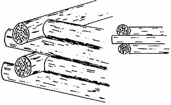
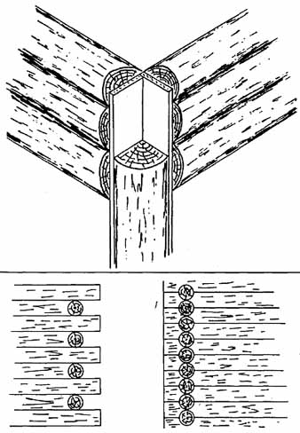
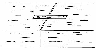
The cracks between the logs—or in good construction, the seams—are filled with chinking, which traditionally has consisted of just about any material and method that happened to be handy. The usual system in the early days was to jam in moss and then plaster it over with mud or a mixture of clay and twigs or hay. This system obviously was not very permanent, and in fact patching and replacing it used to be an annual spring chore. Another method, some times used today and effective if done right, is to load seams or spaces between logs with a filler of some sort—moss, oakum, clay, mortar, fiberglass, or mineral wool have all been used—and then nail fully-round lengths of saplings or strips of narrow board over the joints (Ill. 6-22). This makes a reasonably tight seal and sheds moisture fairly well. If the strips are nailed into only one or the other of each log pair instead of both, the logs can move from expansion, contraction, and shrinkage or settling without tearing the joints completely apart.
Another possibility with fully round logs is to first allow the logs to undergo most of the settling and shrinking that will take place by letting the structure age for a year or so before chinking. Then wood wedges made from shingles or clapboards are driven firmly into the spaces as necessary. The next step is to plug the interior portion of the joint space (working from the outside) with a layer of mortar or stucco. Then a narrow strip of wire lath, screening, or hardware cloth is tacked or stapled along the entire length of each joint. Finally, each joint is plastered with another layer of mortar or stucco ( Ill. 6-23).
An ordinary mortar mix can be used for this procedure, made by mixing either from bulk ingredients or using bags of dry-mix. This results in a cement-gray joint. Pure white joints can be made by using a white mortar or stucco mix, and various color tones can be made up by adding the proper dyes to the mix. The mortar joint should be indented slightly at the top and slant outward and downward to the bottom in order to shed moisture rapidly. This is an effective method of sealing that will endure for many years if regularly maintained as necessary.

Ill. 6-22. Round logs sealed with caulking and a cover
strip or sapling.
Ill. 6-23. Round logs chinked with wood wedges and sealed with mortar or chinking compound retained by screening.
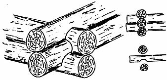
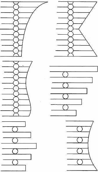
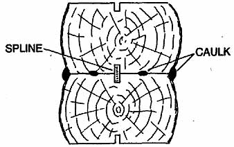
Round logs can also be put together with a center spline ( Ill. 6-24). Do this by first slightly flatting the logs top and bottom and rough-matching and aligning them in place. Then cut a full-length groove the length of the top and bottom of each log. Mating grooves, of course, must match up. The width of the groove should be at least ¼ inch, but can be made to match any size of readily available spline material. A depth of about 1 inch is plenty, but more is fine. If the logs are green, the spline should fit a bit loosely in the grooves to allow for some shrinkage. The spline in fully cured logs should be fairly snug, but not a jam fit. This center spline aids in holding the logs in position during construction, helps to keep them aligned permanently, and serves as an additional weather seal. A thick bead of caulking or a layer of mortar or mastic can be added along the seam on either or both sides for the final sealing.

Ill. 6-24. Flatted logs splined and sealed with caulk,
mortar, or chinking compound.
Ill. 6-25. Cupped logs sealed with caulk, mortar, or chinking compound.
Ill. 6-26. V-notch joint filled with insulation and the joints sealed with caulk, mortar, or chinking compound.
Another procedure that is used with round logs, making an effective joint and seal, is shown in Ill. 6-25. The log bottoms are cupped with a gutter adze and trimmed along scribed lines so that each log fits snugly upon the log below. Often called the Swedish cope because of its origin, this construction is very sturdy and provides an airtight seal that sheds moisture extremely well. The job is finished by running a heavy bead of caulking along the seams both inside and out. A variation is to make the cup slightly deep, leaving a hollow center channel which is then filled with fiber glass insulation for added protection.
The V-groove joint, a Norwegian style, is similar but somewhat easier to make in that a power saw or a mill can be used to do the initial cutting. The log consists of cutting a deep V-notch in the bottom of each log, following lines scribed from the log below to make a con toured fit. The hollow portion of the notch can be left empty, or stuffed full of fiberglass or mineral wool insulation. To hold the insulation in place as the log is rolled into position, first staple a strip of cheesecloth along the groove edges to serve as a retainer. Seal the seams on both sides with a narrow bead of caulking worked well into the slight gap along the V-edges ( Ill. 6-26).
Another possibility is to cut the top of each log to an A-shape, and incise the bottom with a V-groove. The angles should be broad; by making the A-angle a degree or two shallower than the V, the joint will pull together well when the logs are spiked in place. The cuts need not be made along scribed lines, but the logs should be of reasonably uniform taper and diameter. This makes a tight and solid joint that sheds moisture very well and keeps the logs aligned. The seams are deep enough that a bead of caulk or a layer of mortar can be easily applied ( Ill. 6-27). One drawback is that some edge portions of the A-cut might be visible. However, the sharp edge can be planed to a curve and faired in.

Ill. 6-27. Logs joined with mating V’s and sealed with
caulk, mortar, or chinking compound.
Ill. 6-28. Flatted logs splined and sealed with weatherstrip or caulk between, with caulk at the joints.
Ill. 6-29. Flatted logs double-splined with three interior
strips of caulk or weatherstrip, caulked at the joints.
Flatted logs are much easier to build with and to join and seal than round logs. The wider the flats are the greater the stability of the walls and the easier the logs are to join and seal. One common arrangement is to provide a center spline between each log by grooving down the top and bottom center lines. As each log is set, a bead of caulk is run along the top surface of the log below, on each side of the spline. The weight of the logs presses the caulking out into a wide seal. An additional bead of caulk can be run along the seam on one or both sides. This combination makes a very weathertight joint ( Ill. 6-28).
If the flats are wide, the system can be modified to provide an even better seal. Set a double spline between the logs, with three beads of caulk spaced across the flat. Then add another line of caulk on both the interior and exterior seams ( Ill. 6-29). This requires extra time and materials, to be sure, but makes an excellent seal that should remain effective in definitely.
Where the logs are flatted on three sides, a double or triple caulk bead—with or without one or more splines—plus a caulk bead along the outside seam and a batten nailed as a cover over the inside seam, makes an effective arrangement ( Ill. 6-30). If the appearance of interior battens is objectionable, an alternative is to make a deep bevel on the inside log faces. This forms a small V, along the bottom of which a bead of caulk is run. The V is then filled with a strip of matching molding, placed flush for a smooth effect or inset slightly for a shadowline effect ( Ill. 6-31).
Regardless of the shape of the logs or the form of the joints between them, many log house owners prefer the visual effect of relatively wide bands of chinking between the wall logs, whether needed for effective sealing or not. There are new chinking materials now available that can be used even for joint lines too narrow to hold mortar, as well as for wide joints and for re-chinking over old materials. These are quick-drying, lightweight, mortarlike compounds that are easy to apply, ad here tightly to the log surfaces, and remain flexible; they will not crack or pull away. They are also very long-lived and virtually impervious to the weather.

Ill. 6-30. Three-flatted logs splined and sealed with caulk
and weatherstrip, and battened at the inside joints.
Ill. 6-31. Three-flatted logs splined and sealed with weatherstrip and/or caulk, with an inset decorative molding or an open V at the inside joints.
SECURING LOGS
The most common method of securing logs is to spike them down tight. This is usually done about every 3 or 4 feet along full-length logs, and wherever necessary to secure short pieces. One spike at each nailing point is sufficient, driven straight down through the middle of the log or slightly offset to clear splines. The spikes should be long enough to extend at least l way into the log below. Ordinary round spikes are fine, but spiraled spikes drive more easily. They also hold tighter because of the way they screw themselves into the wood.
Drilling pilot holes for nails is not usually necessary, especially in most softwoods. With spikes, the situation varies. Generally pilot holes are necessary, especially when the wood is dry, hard, or a species prone to splitting. Pilot holes should always be drilled when the spike is being driven close to the end of a log, or near or in a joint. They might not be needed in very green or soft wood. The pilot holes should be somewhat smaller in diameter than the spike. They extend through the log being fastened down but just a bit, if at all, into the holding log. Shorter spikes can be used by drilling a pilot hole first, then boring the hole out larger to the diameter of the spike head, about one third of the way through the log. The spike can be driven down into the log with a drift to seat at the top of the pilot hole. A 6- or 8-pound sledge is usually ample for driving spikes. When working green wood, make the pilot hole size about the same as the spike diameter. When the wood cures and shrinks it will grip the spike tightly but is unlikely to split at the hole.
Dowelling is another effective means of securing logs. This involves drilling holes at intervals through all the logs, slightly oversized and carefully aligned so that they all match up. Thick hardwood dowels or rounds are inserted into these holes ( Ill. 6-32). The fit is snug but loose enough so that as the building settles the logs slip down on the dowels. Steel rods could be substituted for the wood rounds.
Ill. 6-32. This cutaway shows a method of strengthening
and securing log walls with dowels.
A variation on this theme is to drill smaller holes that align from top to bottom of the wall, positioned close to corners and at 3- or 4-foot intervals. Long steel rods threaded top and bottom are inserted in the holes and secured with nuts and washers. Bolt pockets must be formed in the top of the foundation if it is a continuous- wall type, positioned to allow free access from the inside, under the floor. After installation, the bottom nuts are tightened every two or three months for a few years until the structure is fully settled out.
Yet, another method uses steel cable and turnbuckles. The cables are actually tie-downs, anchored at one end to the roof frame at each exterior corner. The bottom end is attached to a turnbuckle which is in turn attached to a sturdy anchor bolt built into the floor frame, or preferably the foundation or a deeply buried deadman. The turnbuckles are taken up periodically and kept taut as the building settles, compressing the wall logs firmly together. This is a good method in high-wind country.
THE PLATE LOG
When you reach the top of the walls, the last log to be placed is the plate log. This is the log upon which the roof rafter ends will rest. The extent and position of the plate log varies. In a rectangular house with a typical gable roof, for example, there will be a plate log across the top of the front wall, and another across the back, both at the same level; the end walls just keep climbing to the peaks of the gables. If the house is rectangular with a hip or mansard roof, sill logs will go all the way around the top at the same level. On a house with a shed roof, or a saltbox style, the plate logs will be at front and back but at different levels.
Whatever the case, the plate logs should be specially selected for straightness, uniformity of taper, and soundness. They must be fitted with great care so that the corner tops are at an equal height from the floor line, the top surfaces are level and all in the same plane, and the angles of all exterior wall corners are on tar get (usually 90 degrees). This is the last chance to make sure that there will be no difficulties in building the roof, and the roof alignment will be correct and not racked, cockeyed, sway- backed, or otherwise out of true.
In some round-log constructions the plate log is left fully round. When the rafters are set, whether round logs or dimension stock, the plate log is notched to accept each individual rafter. In some smaller buildings no rafters are used; instead the roof sheathing is secured to purlins that parallel the roof ridge. In that case, the eave ends of the roof sheathing boards are simply nailed directly to the plate log. In most cases, however, the plate log is flatted at least on the top, often on the top and exterior face, and in flatted-log construction on three faces. Then the rafters are either cut off at an angle and seat directly on the plate log with no overhang, or more commonly are notched with a bird’s mouth to rest on the plate and also over hang to form the eaves. More information on this part of the construction will appear in Section 8.
At this stage, the key point is that when you have finished laying the plate logs, if you were then somehow able to drop a huge lid over the whole structure the under surface should lie down snugly all around and the top surface should be as flat and level as a pool table.
STOCKADE CONSTRUCTION
Though the majority of log buildings are constructed by stacking the logs horizontally one on top another, they can also be placed vertically in stockade construction. This is a less common method. It has a somewhat unfamiliar appearance, reminiscent of pioneer fort days, but nonetheless is attractive and has some ad vantages for the do-it-yourselfer.
Corner construction is simple in this type of building. Either full or split logs can be used, and because the lengths are short they can be handled and installed by one person (at least in the smaller diameters). The logs can be of small diameter as well as short length, and so might be more readily available and/or less ex pensive. Settling is not a problem, because logs shrink mostly in volume and hardly at all in length. Extensive shaping, joining, and splining is not necessary, though all three are or can be done to some extent. About the only cutting that really has to be done, depending upon the construction details, is to square the log ends and perhaps do some trimming and fitting around window and door openings. This method can also be used to build walls that are extremely thermally efficient and will meet or exceed the strictest building code requirements.
The foundations needed for stockade log construction are essentially no different than for the horizontal type. With pier or post foundations, however, the spans must be kept quite short and/or the sill beams or logs quite sturdy. Floor frames made from dimension stock should include built-up headers made from three or four layers of planks. This is because the weight distribution and downward press of a stockade wall is different than for horizontal construction; while horizontal logs are partially self-supporting, the vertical ones are not. There is one further detail to add: metal flashing strips between the wall and the sill to prevent moisture from seeping into the structure.
The simplest type of vertical log construction is to stand a single row of fully round logs up on the sill and run a plate plank, beam, or log across the top (Ill. 6-33). The logs can be toe-nailed or pinned at the bottom, and are spiked through the plate at the top.
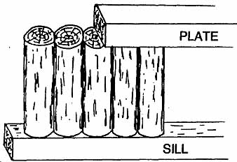
Ill. 6-33. A single-thick, full-round log stockade construction.
This method carries one of the problems of fully round horizontal log construction:
Shrinkage is bound to occur and open up the seams between the logs. Effective sealing is difficult, and the overall construction is not particularly weathertight. Sealing at the sill is difficult, too, and the flashing installation is troublesome and unsightly. At best, the logs should overhang the sill by a considerable amount to reduce the possibility of moisture entering. Liberal amounts of caulking and chinking must be applied, and then maintained religiously. Flatting the logs along their sides helps, and splining and double sealing with caulk beads makes for a much more weather proof wall.
Another possibility, considerably more weatherproof, thermally efficient, and airtight, can be made by erecting a double wall ( Ill. 6-34). This has the disadvantage of using more material (though the logs can be slimmer) and involves added labor, but is also a tremendously strong method.
Single-thickness sills should be provided at the bottom and double-thickness plates at the top. The logs are flailed on three sides for a tight fit. They can also be splined between logs if desired, and single or double beads of caulking laid as construction progresses, at least on the outside course.
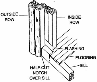
Construction begins by setting the outside logs in place in a continuous row, allowing them to overhang the sill corner by a consider able margin. Continuous metal flashing should cover the outside face of the sill and be bent back over the sill top beneath the wall logs, and then bent up between the two rows. Half-cut the bottoms of the outside logs to notch over the sill ( Ill. 6-35). Nail the log bottoms directly to the sill and spike the tops down through the plates. Attach a core of exterior-grade plywood to the interior faces of the logs. Leave a ½-inch gap between all plywood joints (including top and bottom) and fill these cracks with flexible silicone caulking.
Erect another row of logs on the interior side of the plywood, toe-nailed into the sill at the bottom and spiked through the plate at the top. Or, if the interior decor is not to be log- oriented, simply furr out the plywood surface, add insulation, and cover with paneling or wallboard to give the appearance of a conventional interior wall.
Ill. 6-34. Double-thick, three-flatted log stockade construction.
Ill. 6-35. This cutaway of a double-thick stockade wall
shows the assembly arrangement.
Split half-logs are easier to handle, require less material and so are less costly, and make an equally effective stockade construction. Slabs will work also and are even less expensive. However, they are much thinner and take a lot of trimming and shaping, and their structural strength is about nil.
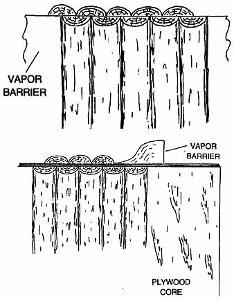
The simplest construction starts with a row of half-logs, spiked to the sill at the bottom and spiked through the plate at the top. Staple a layer of tarpaper or construction plastic across the inside of this exterior wall. Toe-nail and spike another row of half-logs into place on the inside with the joints staggered ( Ill. 6-36). The two layers can be nailed together for added strength. Nailing is done from the outside so that the nailheads don’t appear as part of the interior decor.
Ill. 6-36. A staggered half-log, double-thick stockade
wall with an integral vapor barrier.
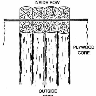
Ill. 6-37. A staggered half-log, double-thick stockade wall incorporating a vapor barrier and a plywood core. Slab facing could also be used in this construction.
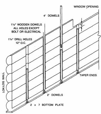
A variation on this theme makes use of a plywood core sandwiched between the two rows of logs. In this case, the interior row of logs can be set first by toe-nailing at the bottom and spiking through the plate at the top. Then nail the plywood to the faces of the in tenor logs, so that no nailheads are visible from the inside. Staple a roofing felt or construction plastic vapor barrier to the plywood core, the face of which should be flush with the exterior face of the sill. Nail the outside layer of half- logs to the plywood and to the sill face, with the bottom edges extending just below the sill bottom ( Ill. 6-37).
This type of construction can be expanded slightly into a core wall with as high an insulating value as you wish. The core is nothing more than an ordinary stud wall built from dimension stock, just as in any ordinary platform-framed house.
To gain a high R-value, 2- x -6s or 2- x -8s can be used when the core is filled with a full- thickness layer of fiberglass or mineral wool insulation. The outside of the core frame is covered with plywood which extends from the top of the plate to the bottom of the sill. Nail half-logs directly to the plywood in the form of a siding material ( Ill. 6-38). In this instance, slabs can be used equally well. The slab edges can be trimmed and squared for a better fit, and laid either horizontally or vertically. After the core is filled with insulation, staple a vapor barrier of plastic sheeting to the studs, and apply an interior wall covering. This might consist of standard plasterboard or paneling as in a conventional house, or an inside layer of half- logs or slabs.
Some of these constructions, as you can see, are not really log houses. But they are interesting and perfectly livable styles that at least have the log appearance.

Ill. 6-38. A thermal core wall faced with matched slabs.
PIECE-EN-PIECE CONSTRUCTION
Piece-en-piece construction is a method seldom seen in this country, but it is an old and well- known method in other parts of the world. It is relatively easy to do and makes a sturdy and handsome structure ( Ill. 6-39). For this method, logs that are flatted on two or three faces, or beams or timbers can be used. Log thickness should be at least 5 inches in order to make effective joints; 7 or 8 inches or more is preferable. One advantage of this type of construction is that the entire structure can be made up from short chunks of logs, but with out any splicing. The sections can be as short as 2 feet, or extended to 6 feet or more if desirable.
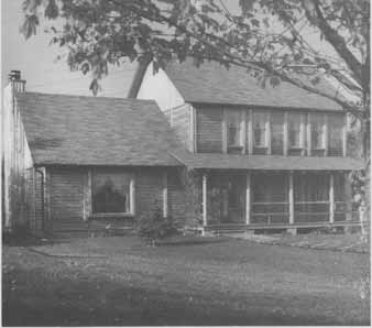
Ill. 6-39. This log house was constructed with a modified
piece-en-piece system called post and-sill, incorporating a thermal
core in the exterior walls.
The corners of the structure can be made with one of the notched log arrangements as discussed earlier, but usually feature full corner posts. The posts contain two deep, wide grooves at a 90-degree angle to one another and are shaped to a stout tenon at top and bottom. The tenons fit into mortises in the sill and top plate. The plates, sills, and posts can be logs or beams. A series of similar posts is set at the desired intervals along the sill, each with full- length dados or grooves opposite one another and parallel with the sill.
The wall logs are squared and tenoned to match the grooves and slid down into place one on top of another, and fitted to nest tightly as they are placed ( Ill. 6-40). The wall logs should be flatted top and bottom for best results, and may also be splined and/or sealed with beads of caulking. The logs can be spiked together, but should not be attached in any way to the posts. This leaves them free to settle within their framework as they will. The last step is to install the top plate log or beam to tie the entire framework together. Various sealing, flashing, and caulking methods are used as necessary to make the structure weathertight and moisture-resistant.
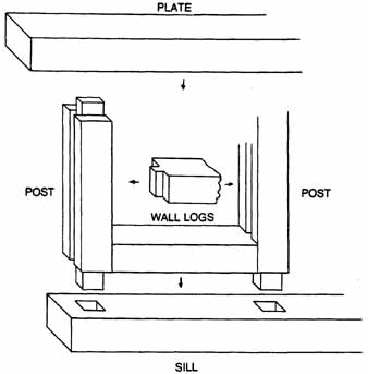
Ill. 6-40. A typical piece-en-piece or post-and-sill log
assembly method.
DOOR AND WINDOW ARRANGEMENTS
There are several approaches to cutting doors and windows in a log house. As far as which one to pick—they all have their advantages and disadvantages. A lot depends upon your over all construction methods and whether you in tend to make your own doors and windows or buy ready-made units. Whatever your choice, there is one very important point to keep in mind about all door and window installations in log houses. As shrinkage and aging occurs, settling takes place, Furthermore, there is also a certain amount of expansion and contraction in the large mass of solid wood that surrounds the doors and windows, and it is not uniform from component to component. This means that allowances should be made, and that installation procedures are considerably different than in a conventional frame house.
There are some builders who claim that the only way to build is to spike, bolt, and nail everything into place rigidly so nothing can shift. Perhaps that system has worked for them, but in this case two factors must be taken into consideration: The first is that the log house kit manufacturers, after years of study, designing, testing, and experience, use construction procedures that allow for shrinkage and settling. They know it will happen, and have taken steps to allow it without causing dam age or problems. The second is that for centuries European log builders have always made such allowances. They have always been such superb craftsmen, and knew their woods and their construction methods so well, that they could tell to within a fraction of an inch just how much settling and shrinkage would take place at any point in a building. They not only provided slip joints wherever necessary, they also made all the corner and other joints loose by a calculated amount so that in due course the joints would properly tighten up to just the right degree. In the face of this sort of evidence, it would seem unreasonable not to follow the same course and make the necessary shrinkage and settling allowances.
Exceptionally well-dried logs in a fairly humid climate might shrink and settle as little as /8 inch per foot of wall height over the first couple of years, partly from compression. But that is not much for log construction, and most will settle more. Large logs that are less than half cured can easily shrink and settle as much as ¾ inch per foot of wall height. What this means is that if you start off with a ceiling height of 8 feet, within two years or less the ceiling will lower to 7½ feet. If you arrange neat openings in the log walls and fit doors and windows snugly into them, not much time will pass before you have smashed windows and buckled doors. The force of the settling logs is tremendous and no amount of light framing or bracing can withstand that kind of pressure. Therefore, above each door and window there must be a substantial space at the outset to allow the logs to settle down around the window and door frames.
There are at least five different ways to go about cutting in doors and windows. One is to build the wall up solid, leaving no openings at all to begin with. When the walls reach full height, or at any time afterward, cut the openings in with a chainsaw. Notches big enough to start the saw in are often left as markers at the window or door opening tops; these are preplanned and cut when that particular log is reached as the walls are laid up.
Cutting is done from the inside, where the sawyer has a flat, solid floor as a working plat form. The openings should be outlined by boards nailed into exact position; these also serve as guides for the saw blade to ensure straight cuts. This system works particularly well in smaller structures where the logs are mostly or entirely full-length.
The big advantage to this method is that the wall logs can be stacked up rapidly with out stopping to fool around with small pieces between windows and doors and corners, that have to be propped and braced until everything gets tied together. The disadvantages are that you are forever crawling over the walls to get inside the structure. Also, you have to remember to drive spikes and secure the logs in every course or round close to where the opening will be—but not within the opening or right on the saw-cut line.
Size the openings to accommodate what ever factory-built window or door units you plan to use, plus the thickness of the bucks, and the slip-joint elements if they require extra room. Or, they can be cut to any reasonable size if you plan to build up your own doors and windows.
There are three schools of thought about placement of the openings. One says that they should fit between the upper and lower logs without cutting into either, which can be a problem if you are using stock units. Another says that for windows you should always leave the header log above the window header uncut, but cut about a quarter to a third into the lower one and carve it away on an outward slant to provide a tight, flat fit for the window sill and to allow good water-shedding. The third says cut upward about a third of the way into the log above the window or door, and into the bottom log a little if you must.
All of these work. Whichever you choose, there should be at least one full-thickness log above every opening. Door sills are usually notched into the structure sills on an outward and downward angle. This, however, can depend upon the specific design and construction of the door and its frame. The standard angle of pitch for a door sill is 12 degrees, and 6 degrees for a window sill, but you will incur no penalties for using other angles.
Another method of making provisions for doors and windows is simply to cut the logs to the proper lengths to form the openings as the log courses or rounds are laid up. Window and door locations are mapped out ahead of time, and when the correct points are reached the logs are cut to suit. Window openings are started when the correct height above the floor is reached. The bottom of the window openings usually coincide with the top of a particular course, especially if the logs are flatted, but they can also be notched into the logs if desired.
Sometimes only the window and door frames, called bucks, are set in place as the construction proceeds. Door bucks are stood up be fore the walls are even started. They are secured at the base and leveled, plumbed, squared, and solidly braced with angled boards tacked at the top of the frame at one end and into the floor at the other. The logs are fitted and built up around the frames. Window bucks are placed when the proper course height is reached, and are set and secured in the same way as the door bucks. The log courses are built up around them. Because the bucks are empty, there is no danger of damage to the windows and doors themselves during construction. Cross-bracing is often installed inside the bucks to make sure that they stay in square and do not bow in as the wall logs are run up against them.
A system that is often used, particularly with kit log houses, is to set the complete units in place as construction goes along. The doors are set before the walls are started, while the windows are placed when the appropriate course level is reached. This method requires an extra degree of care and caution. The units must be precisely set, and ruggedly braced so they cannot move. Cross-bracing of the assembly frames is an excellent idea wherever possible, so that the sides don’t get pushed in and render the units inoperable or damage the frames. The units must also be kept fully in square so they don’t jam up. Taking pre-manufactured door or window assemblies apart after the units have been installed in order to plane or trim them down so they will work properly is a miserable job.
Take care during construction that the units are not damaged in any way. Doors are not quite so much of a problem, but windows are very tender. Sometimes it is possible to re move sash sections and glass without much difficulty, and store them in a safe place. Other wise, covering the units on the inside with scrap pieces of plywood works well. The butt end of a log rammed through a big casement window won’t do it or your blood pressure much good.
No matter the approach you choose, every door and window opening and installation must have a substantial allowance built in above the head jamb for the inevitable log settling. The side jambs must always be installed in such a way that they are solidly set, but still allow the logs to slip down as they settle. There are a number of possibilities in providing doors and windows with slip joints and several methods for installing them. Section 9 contains details on this subject.
PREV: The First Floor
NEXT: The Second Floor
© CRSociety.net