Once the foundation is complete, the next step is to build a floor frame for the first floor level. Occasionally in small log structures with exceptionally shallow crawl spaces beneath, the walls are laid up and the first floor installed later. However, in nearly all cases it is advisable to build the entire floor frame and cover it first, so that you have a convenient and stable platform upon which to work.
There are several ways to go about constructing a floor frame and a good many variations on each, depending upon the specific house design. But no one method is necessarily better than another, so you have a free choice. There are also several ways to go about laying flooring. Whatever combination you choose, the object is to provide a level, smooth, strong floor, vibration-free and with a high degree of stiffness. There are few things worse in a house than a rubbery, sagging floor, and this is usually difficult to correct later.
The following arrangements are basic, and all are widely used in log house building. Construction variations and detail changes can and should be introduced wherever necessary or desirable.
LOG FLOOR FRAME
The combination of log sills, joists, and girders is a time-honored one which originally came about because of a scarcity of sawed planks and a plenitude of logs. This is a sturdy system that allows fairly long joist spans and spacing, de pending upon the log joist size.
The starting point is the single layer of logs that lie directly on top of the foundation, called sill logs. For this purpose, select your longest, straightest, and best logs with the least amount of taper. On continuous-wall foundations, short sill logs can be spliced together at any point. On pier foundations, short logs must be spliced together directly over a pier. Wherever you can, though, stay away from splicing, because this involves extra work and also creates a weak spot in the structure.
The bottom of the sill logs should be flat ted along their entire length when set on continuous-wall foundations, for ease of working and a generous bearing surface. If the sill logs are set upon piers, they need only be flat ted on their bearing surfaces. If you wish, in both cases the flatting can be done so as to compensate for log taper, so the sill log tops will be level all the way around. Note, though, that if the rest of the wall logs have a fairly pronounced taper and the sill logs do not, the appearance will not match up. No construction difficulties will be caused, however.
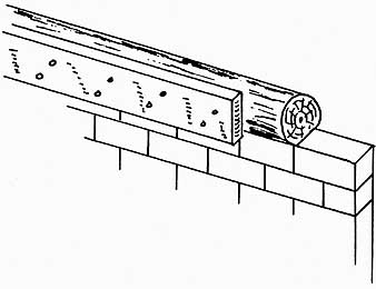
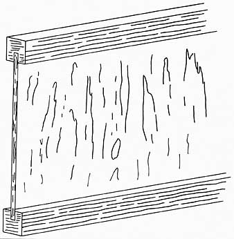
Lay the sill logs upon the long sides of the structure first. If tapered, opposite logs should always be placed with their butts/tips opposite: on the near-side wall, butt left; and the far-side wall, butt right, or vice versa. Lay out and drill the anchor bolt holes, slightly oversize to al low for some adjustment. The tops of the holes can be countersunk so that the nut rests below the log surface, or recesses can be made in the next round of logs to accommodate the bolt ends and nuts. In the case of continuous-wall foundations, place a layer of sill seal on top of the foundation. A strip of fiberglass insulation ½ to 1 inch thick works nicely for this, and fills and seals off slight irregularities. Set the log sills in place and tighten the anchor bolt nuts down firmly ( Ill. 5-1).

Ill. 5-1. The sill log is anchored to the foundation
wall with sill seal sandwiched in between. The taper of the log is exaggerated
for illustrative purposes.
There are several ways to make sill corners. Most log walls use jointed corners with the log ends—the endwork—protruding in both directions. The sill can be made in the same fashion as the remainder of the log walls, in which case the sill logs will simply extend beyond the foundation corners for the desired length ( Ill. 5-2). Logs that are flatted top and bottom and are of relatively uniform thickness usually are set with a joined corner. In this case, the long log sills protrude beyond the foundation corner, but mortises are cut first so that tenons of the short sill logs will fit in ( Ill. 5-3). The short sill logs do not extend beyond the foundation corner, but subsequent wall courses do, alternately. Corner-post construction requires that the sill logs stop short of the foundation corners with the ends cut exactly to accommodate the corner posts ( Ill. 5-4). These are sometimes installed first, but often after the sill logs. Full details of the various corner constructions and endwork are covered in Section 6, and will have a direct bearing on exactly how you set your sill.
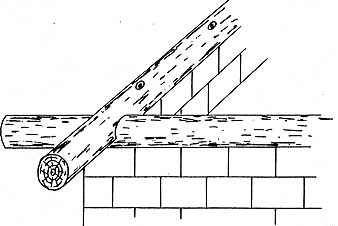
Ill. 5-2. In this log sill corner, both logs are extended
past the foundation.
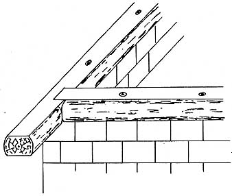
Ill. 5-3. This type of log sill corner is made with
one log ex tended beyond the foundation and the mating log tenoned into
a mortise.
The short sill logs are set next. In corner- notched construction these sill logs will also protrude beyond the corners of the foundations, overlapping the long sill logs. Align them and cut the necessary corner notches and set the logs in place. Bolt them down and spike the notched ends together. Tapered short sill logs should be placed with opposite butt/tip ends, with their tips notched into the butts of the long sill logs. Thus, tapered logs always follow each other around the foundation tip to tail, like elephants in a parade. If the sill logs run clockwise, the second round will run counter-clockwise, or vice versa, and alternate on every round.
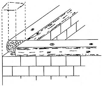
Ill. 5-4. Full corner posts are used in this kind
of log sill corner.

Ill. 5-5. Saddle-notched sill logs leave a gap that
must be filled, or compensated for when the foundation walls are built.
Setting round or bottom-flatted logs in half-notched style results in a gap between foundation and log at the two ends of the structure that is roughly a half-log width ( Ill. 5-5). In a continuous-wall foundation this can be corrected by preplanning and adding an extra half-block (or half-log) of height to these foundation walls during construction. This can also be accomplished by placing a split half-log in these locations, or by filling the gap with mortar or concrete afterward. With pier foundations, the short-wall piers can be made higher at the outset, or shim blocking can be fitted between the pier top and the sill log bottom. Sill logs flatted top and bottom and mortise-and tenoned at the corners will come out level.
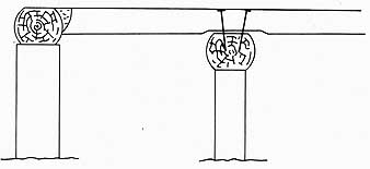
Most plans also call for one or more girders to help support the floor joists. Girders can be set in pre-planned notches in the foundation walls, calculated so that the girder tops are level with the floor joist bottoms ( Ill. 5-6). This type of girder is set before the sill logs are placed. Girders may also lie wholly within the foundation, attached to piers or other supports. In that case, they can be installed after the sill logs are placed. They may, in fact, be attached to the sill logs themselves at some points ( Ill. 5-7). In any event, girders must be secured in place before the floor joists can be laid down.
Log joists are usually made from smaller log sections about 6 to 8 inches in diameter. Spans should not exceed 10 feet for this size, and even this short length is apt to make for a springy floor, depending upon the relative stiffness of the wood species. Each joist should be flatted the full length and a minimum of 2 inches wide to receive the flooring. The taper in the joist logs can be compensated for as the flatting is done, or the joist ends can be set so that the flat is level. One end of each floor joist is cut to a squared tenon, which will fit into a matching mortise in the sill log so that the flatted surfaces of each are flush ( Ill. 5-8).
If the opposite end of each floor joist log is held by a girder placed at the same level as the sill log, that end is also tenoned and the girder mortised in the same fashion. If the joist log lies on top of a girder set at a lower level than the sill, it must be accurately flatted on the bottom to lie level and even upon the girder when spiked into place ( Ill. 5-9). Some amount of shimming might be necessary to bring all of the joists into accurate alignment. Flatting should be done with caution, however, so as not to take away so much wood that would weaken the joist at its bearing point.
The mortises are usually spaced on 16-inch or 2-foot centers along the sill logs, and also in girders as necessary. The bottom of the mortise cuts may or may not be on a level line; they may be cut to fit each tenon individually.

Ill. 5-6. A girder notched into a foundation wall
should be calculated to be level with the floor joist bottoms.
Ill. 5-7. In this arrangement the girder is notched
into the sill log with its top level with the sill tops.
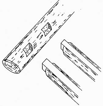
Ill. 5-8. Joist logs can be attached to the sill logs
with a mortise-and-tenon arrangement.
Ill. 5-9. Flatted logs mortised into the sill logs
and resting on top of a girder log should be shaved or shimmed as necessary
for a level fit.
Note too that the mortises may or may not be the same distance from either the top or the bottom of the sills, depending upon the taper of the logs and the varying sizes of the joist logs at the tenons. The object, however, is to line out a level and even floor by setting all of the joist tops in the same plane.
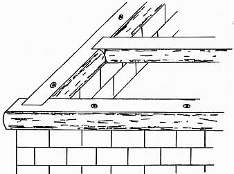
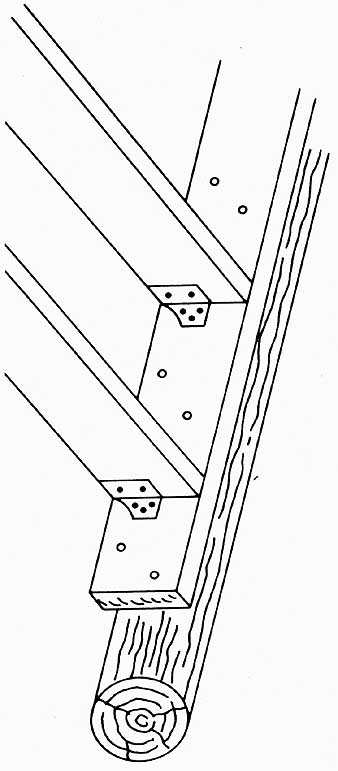
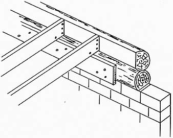
One drawback—aside from the amount of work involved—in tenoning the joist ends and mortising the sill logs is the loss of strength from cutting away portions of the logs. Each log then has only the strength attributable to the size of the tenon, not the uncut portion of the log itself. An alternative method that retains the strength of the log and at the same time allows the use of somewhat smaller logs for the same conditions, is to saddle-notch the joist logs close to their ends so that they will lie on the sill logs ( Ill. 5-10). Thus on the long sides of the building the joist logs protrude through the wall and are visible from the outside.
This is a strong and sturdy system, but also creates a few problems of its own. Some of the second-round logs must be saddle-notched to accommodate the top portions of the joist logs, and exact fitting is not an easy job. Also, the added joints and the protruding joist ends afford a number of additional spots for moisture to attack the structure. The joist logs can also be extended several feet, be supported at their ends by piers or posts, and form the floor frame for a porch that would protect them anyway.
In any case, after the joists are trimmed, fashioned, and fitted (or as you go along), set them in place and check for accurate level by using both level lines stretched across the structure and a long spirit or hose level. Shim up or pare down slightly as necessary, and when each joist is just right, secure it with one or two spikes driven into the sill or girder. Bear in mind that when you do so, you will probably settle or compress the joint somewhat, depending upon the species of wood. You might find that each joist face will have to sit just a tiny bit high in order to be flush and properly level when spiked down. Also, if there is any danger of splitting (some kinds of wood split much more readily than others), drill pilot holes for the spikes first. Figure 5-11 shows a typical log floor frame layout.
LOG AND DIMENSION-STOCK FLOOR FRAME
Dimension stock is the term given to standardized lumber that is 2 to 4 inches thick and 2 or more inches wide. Stock less than 2 inches thick is called board or plank, while that over 4 inches is called timber. Rough-cut, full-sawn dimension stock is left rough from the saw and can be cut to any dimensions, but usually follows an even thickness of 2, 3, or 4 inches and widths in even increments of 2 inches. This stock can be bought through lumberyards on special order, or purchased directly from saw mills. Nearly all dimension stock purchased from lumberyards has been planed on all four sides (occasionally on three) and is called S4S (or S3S). It also is somewhat smaller than its nominal or named dimensions—trade size— would indicate. Thus, a 2 x 4 actually measures not 2 inches by 4 inches, but approximately 1-5/8 x 3½ inches.
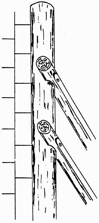
Ill. 5-10. Joist logs can be saddle-notched over the
sill logs and left to protrude on the exterior of the building.
The combination of log sills and dimension-stock joists is a commonly used one because the floor frame goes together much more easily and rapidly than does an all-log floor frame. The S45 variety of dimension stock is the common choice because it is readily available and can be quickly assembled into a level, uniform, and strong structure. However, rough-sawn stock from local mills is frequently less expensive and nearly as easy to handle, and is just a bit stronger per nominal size be cause the actual size is greater. You can also cut your own dimension stock from logs you have felled yourself by slicing them up with a chainsaw mill. Or, you might be able to arrange for a local sawmill to cut your logs for a small fee.
Building this type of floor frame begins in the same manner as an all-log floor frame. Set and secure all the sill logs in the same way as discussed earlier. Set any necessary girders as well, positioned to allow whatever joist spans you have decided upon. The spans are variable depending upon the spacing of the joists, the species of wood used, and the dimensions of the joists. Some typical spans are shown in Table 5-1. The girders can either be stout logs or built up from three or four layers of suitable dimension stock nailed tightly together. Either are in turn supported by piers or posts below.
Begin the floor frame construction by choosing a suitable reference point at one corner or another which will be the level guide for the entire floor assembly. Start at this point and spike headers of dimension stock the same size as you have chosen for the joists to the log sill ( Ill. 5-12). The headers run at right angles to the joist direction. Then in the same way spike end joists to the log sills; these lie in the same direction as the joists. Keep a sharp eye on the level of these headers and end joists to ensure that their tops are all at exactly the same height. They must also be kept straight up and down, or plumb.

Table 5-1. Maximum Length of Dimension-Stock Floor Joists.
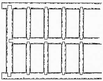
Ill. 5-11. Typical layout for a log floor frame.
Mark off centerlines for all the joist positions along the headers and also on the girder tops. The most commonly used spacing is 16 inches on centers, and this is the most work able arrangement. A 24-inch spacing is adequate in some instances if the flooring is to be a heavy decking material or one of the special plywood systems. The 12-inch centering affords greater strength and stiffness, but at the expense of additional labor and inability to use standard-width thermal insulation batts. Butt the ends of the joists tight against the headers and secure them with metal joist hangers nailed to both the headers and the joists ( Ill. 5-13). Sometimes it is easier to nail the hangers to the joists first, then to the headers. If the opposite ends of the joists lie on top of a girder, they are toe-nailed down with 10d nails, one through the end and one in from each side. If the joists meet the girder, they can be secured with hangers.
Ill. 5-12. A joist header can be nailed directly to the sill log.
Ill. 5-13. A sturdy method of attaching joists to
a header is to anchor them in metal hangers.
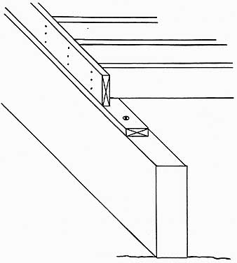
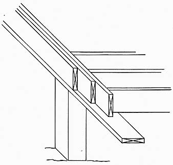
When you are setting floor joists atop a girder, nail in lengths of solid blocking between each pair of joists as you go along. The blocking pieces should travel in a straight line down the length of the girder, and secure them by toe-nailing into the closed end of each block and through-nailing into the ends at the open end of each block. An alternative method is to stagger each block so that if offsets from its neighbor, allowing room (except with 12-inch centering) to nail through the joists and into each end of the blocks ( Ill. 5-14).
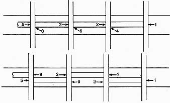
Ill. 5-14. Use this method and nailing sequence for
installing straight-line solid blocking (above) and staggered blocking
(below) between joists. This drawing shows the joists resting upon a
girder, but the same method can be employed in open spans to reduce springiness
and joist twisting.
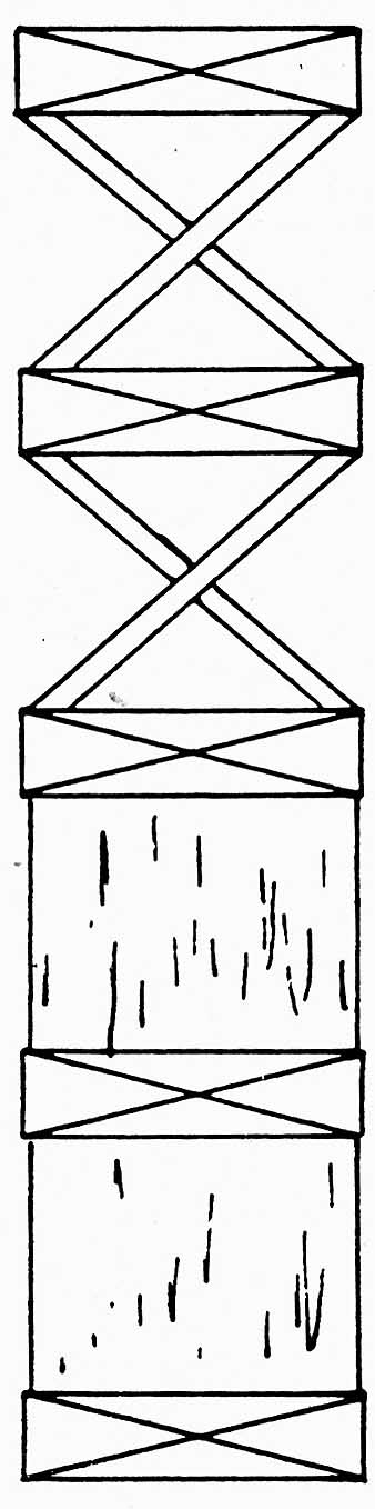
Ill. 5-15. Solid blocking (left) of X-bridging (right),
shown in cross-section between the floor joists, increases the strength
and stiffness of a floor.
After all the joists are set, nail in another run of solid or staggered blocking down the center of each joist span. You can also use X or cross-bridging, which can be made up of lengths of nominal 1- x -4 stock or metal bridging struts made for the purpose. In this case, the upper ends of the bridging must be nailed in place but the lower ends left loose. After the subfloor has been laid, then the bottom ends are secured. In either case, the bridging ties the joists together solidly to reduce warping, add strength, and help to minimize vibration and springiness ( Ill. 5-15).
Joists should not be toe-nailed to headers, because this method doesn’t provide nearly enough holding strength. Another possibility, workable only with small floor sections, is to nail the headers and end joists together in a built-up rectangle, and then nail through the headers to secure the joists. Then the entire frame unit can be boosted into place and spiked to the sill logs. Though this can be (and has been) done, it is a decidedly awkward method and proper fitting and aligning of the frame and sill can be problematic and frustrating.
Another method uses ledger plates. Ledgers are usually 2 x 4s or 2 x 6s spiked to the log sills at right angles to the lie of the joists. The first wall course of logs (or more) is set upon the sill logs, and these logs are flat ted back on the inside face. The joists are set on top of the ledger and butted to the log flat, and toe-nailed to both ledger and log ( Ill. 5-16). The opposite ends of the joists may be handled the same way on a narrow span, or laid across or butted to a girder at some intermediate point.
Ill. 5-16. These floor joists are abutted to a flatted
second-course log and are supported by a ledger strip nailed to the sill
log.
Sometimes another method is used, consisting of a header with a narrow ledger nailed along the bottom edge. The joists are notched to rest upon the ledger and are toe-nailed into the header ( Ill. 5-17). Though this looks like a good arrangement, it isn’t, and should be avoided. If 2- x -10 header and joists are used with a 2- x -4 ledger, a 3½-inch notch must be taken out of the bottom of each joist. The net effect is to reduce each joist to the rough equivalent of a 2 x 6 because a joist is only as strong as its narrowest width will allow. Going to wider joists and headers to overcome this deficiency is just a waste of good material, especially where other, better systems could be used instead.
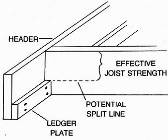
Ill. 5-17. The practice of notching a floor joist,
as shown here, to fit over a ledger plate is not recommended.
DIMENSION-STOCK FLOOR FRAME
A dimension-stock floor frame can readily be made for a log house. It is exactly the same as the system used in conventional platform- framed houses, sturdy and easy to build. There are two basic varieties, one for continuous-wall foundations, and another for pier or post foundations.
On a continuous-wall foundation, the first step is to lay down a continuous sill plate, usually either a 2 x 6 or a 2 x 8. Building codes now require that the plate material be pressure-treated with preservative to minimize rot from damp concrete foundation tops; red wood or perhaps cypress might also be allowable. Either way, the idea is a good one.
The plate lies flat on the foundation top with a layer of sill seal sandwiched between them, and is firmly secured with anchor bolts. Stand a header of the same dimensions as the floor joists up on edge and toe-nail it into position flush with the outside edge of the sill plate. Place these headers at right angles to the lie of the floor joists. Stand end joists on edge and secure them in the same fashion as the headers, to the sill plate and to the headers as well. Line up the joists and nail them into position through the headers and into the joist ends ( Ill. 5-18). Before setting each joist, stand it on edge and sight along it to see whether it is straight, or bows slightly up or down. Then place it so that the crown of the bow is upper most. Secure the joists to girders by toe-nailing, and install blocking between each pair as discussed earlier, down the centerline of each span and along the girders if they are present.
Note that the joists can be full length, reaching from wall to wall but supported by one or more girders beneath and at right angles to them, or they can be short ones that reach only from wall to girder, or girder to girder.
Short joists are easier to handle, but require more nailing. Full-length joists require a little less labor and time, and the effective strength and stiffness is somewhat greater than two or more short ones.
For pier foundations the situation is a bit different. A 2- x -6 sill plate (this may be untreated wood) is first secured flat to the pier tops with anchor bolts. Splicing must be done atop a pier, and requires that two anchor bolts be set. Then the headers are set atop the sill plate, on edge and flush with the outside edge. These headers, though, must be doubled at least and are often tripled in thickness, depending upon the span between piers. The end joists are likewise doubled or tripled, and all are attached to the sill plate in the same way as for a continuous-wall foundation ( Ill. 5-19).
Ill. 5-18. In this system, sill plate and header are
mounted on top of a solid, continuous-wall foundation.
Ill. 5-19. Where a pier foundation system is used,
a full sill beam must be installed, or a sill girder can be made up from
dimension stock.
The headers and end joists can be nailed together first and then set into position on the sill plate. In this case, the joists are attached to the headers with metal joist hangers if the sill plate is the same width as the thickness of the headers, or rested upon the sill plate and toe-nailed to the headers if not. If you would prefer to end-nail the joists, set a single- thickness header back from the outside edge of the sill plate by a distance equal to the thickness of the headers that must be added—that is; usually one or two more headers. Secure that header to the sill plate, then set the joists and nail through the header and into the joist ends to secure them. Nail on the one or two remaining headers, as well as the end joists, so that the outside face of the completed header is flush with the outside edge of the sill plate.
There is an alternative to the multiple-layer or built-up header and end joists, and that is to set a solid-wood sill ‘beam all the way around the foundation perimeter. This requires that suitably long anchor bolts be set when the foundation is built, and the joists must be se cured with metal joist hangers. The sill beam should be the same height, or higher, as the depth of the joists.
There is also an alternative to using ordinary dimension stock for floor joists, and for headers as well. You can use manufactured truss joists of the type designed for residential applications ( Ill. 5-20). These are solid wood and plywood fabrications made in an I-beam configuration, usually about 12 inches deep. They are lightweight but strong and stiff, and are easy to install. Special girders, hangers, and other components are available for use with them. Truss joist sizes should be fitted for each individual job, but you can obtain help from a supplier or factory representative in selecting the correct joists and associated components for your application. This, of course, should be done during the planning stage.
FLOOR OPENINGS
Chances are your floor frame will have one or more openings in it to accommodate a stair way, crawl-space access hatch, chimney, or something of that nature. Such holes require a bit of additional framing.
If the size of the hole is smaller than the space between the joists, all you have to do is nail a framework of the required size, made from dimension stock, into place between the joists. Generally 2 x 4s are adequate for small holes; the principal object is to provide a nailing strip for the flooring edges.
Ill. 5-20. Installing truss joists like this one is
the modern way of building up a sturdy floor frame.
Larger holes that span two or more joist spaces require a considerable amount of extra strength in the framing to compensate for the loss of joist material and continuity. In all-log floor frames, joists that will intersect an opening in the floor are left out temporarily. A pair of header joists is installed with mortise-and- tenon joints between the two joists bordering the opening on each side and at right angles to them, to act as two sides of the opening and forming a rectangle. Then tail joists are in stalled, also mortise-and-tenoned. They run parallel to the main joists and are at normal spacing, from sill (or girder) to header joists on both sides of the opening. If the opening must be narrowed further, a pair of trimmer joists is installed, again with mortise-and-tenon joints, between the two header joists. This construction is outlined in Ill. 5-21, and is not as difficult as it sounds.
The situation is much the same with dimension-stock floor frames, except that all the components are doubled. The outside main joists are installed first, followed by primary headers. The tail joists come next, between the sills or girders and the primary headers. The secondary header joists are then nailed to the primary headers and to the main joists at the ends. Trimmer joists are installed, if necessary, between the secondary header joists. These carry little weight or strain, as a rule, so can be toe-nailed into place from top and bottom. The last step is to install doubling joists along side the main joists, secured at each end and also nailed to the main joists. The diagram in Ill. 5-22 shows how the various pieces go together. For extra strength, you can use metal joist hangers wherever they will fit in.
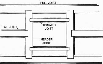
Ill. 5-21. General method of framing an opening in
a log floor frame.

Ill. 5-22. Follow this sequence of steps when framing
an opening in a dimension-stock floor frame.
EXTRA-STRENGTH CONSTRUCTIONS
There are occasions when a lot of extra strength is needed in a floor frame for some particular purpose—often to support an interior partition that is to run in the same direction as the underlying joists. In a log-frame floor system, the partition is best located directly above a joist log, which, if necessary, can be made larger than the other joists.
If this is not feasible, don’t shift the joist spacing around, but instead install an additional joist to lie directly beneath the partition. The same situation is true of dimension-stock floor frames. In this case, though, if the partition is directly above a joist, double the joist. If it is between joists, install an additional double joist to help carry the load. If the partition happens to be a load-bearing one itself, the joists beneath should be further beefed up by tripling or quadrupling the joist to become a girder, or by placing an extra or a larger joist log, or by adding post support beneath.
There are also other reasons for strengthening certain sections of the flooring. A con cert grand piano is a case in point, or a 200-gallon hot tub, or a 1000-pound, slate-bed billiard table. Wherever a semi-permanent massive deadweight of this sort is anticipated, it’s a good idea to double dimension-stock joists, increase log joist sizes, or decrease the joist spacing in that area. Additional post and ‘girder support might also be convenient or desirable. However you do the beefing up, do so to that entire section of floor frame where the load will rest, rather than trying to insert assorted headers and trimmers here and there.
DECKED FLOORING
There are any number of ways to go about laying a floor, but perhaps one of the best uses heavy decking. Standard decking is usually of a 2-inch nominal thickness and 6-inch nominal width, with either one or two matching tongues and grooves that lock the stock together. It is available in several woods, and can be used as a finish floor simply by sanding and applying a floor finish, or it can be covered with another layer of finish floor covering. Decking has tremendous strength and allows for a particularly firm, tight, stiff floor. When used as a finish floor it is both labor-saving and inexpensive by comparison with many other conventional floor systems. Decking can also be laid to provide a finish ceiling below—as over beams between a first and second floor— with another layer of finish flooring applied on the upper or floor side.
To install decking material, first provide a vapor barrier of plastic film if necessary. Then fit the decking piece by piece at right angles to the floor joists. Toe-nail through the leading edges of the decking planks and into the joists for finish flooring, or top-nail where the decking will later be covered. Lock the tongues and grooves tightly together as you go. Make any necessary butt joints directly over joists. Fill out the entire floor area in this way, fitting the decking close to the walls at the edges and trimming around the floor openings.
There is also another type of single-layer flooring that you can use. Though not as thick as decking, planking—which is known as “five-quarter”—makes excellent flooring. This planking is 1¼ inches thick and is surprisingly effective because of certain properties of wood fibers. Without going into great detail, suffice it to say that a single layer of flooring is both stronger and stiffer than two layers of flooring built up to the same thickness.
To give you a comparison, consider a 1-inch-thick board of a particular kind and quality and assign it a strength factor of 100 percent and a stiffness factor of 100 percent. A ¾-inch-thick board of the same kind and quality will be only 42 percent as stiff, and only 56 percent as strong. Two ¾-inch-thick boards laid on top of one another will be ½ inch thicker than the 1-inch board, but will still only be 84 percent as stiff—though about 112 percent as strong—as the 1-inch board. By using a single layer of 5/4 flooring, then, you end up with a floor that is both stiffer and stronger than most conventional two-layer floors, having put out a good deal less labor and usually less cost. This type of flooring is installed in much the same manner as decking, either top-nailing or toe-nailing as the occasion demands. There is a drawback if the floor is to be finished: it must be well protected against damage and staining during construction.
LAYERED FLOORING
The layered method is the more conventional way of installing flooring, and consists of at least two and sometimes as many as four or five layers of material to achieve a finished floor. Though usually involving more labor and greater expense than the single-layer floor, there are advantages of flexibility and convenience, and often this is the only way to end up with the desired floor finish or finish covering. The subfloor layers provide excellent working surfaces where dirt and minor dam age are of little consequence, and there is a wide range of finish flooring that can be applied over the subfloor with whatever variations are desired from room to room or area to area. Furthermore, the finish layers can be ripped up and replaced with new and different materials at any time, something that can not be done with single-thickness flooring (though that can be covered and become a subfloor).
The first layer to go down is called the sub-floor or floor sheathing, and usually consists of either plywood sheets or nominal 1-inch thick boards, often tongue-and-groove. Ply wood saved from concrete forming can be used here. A thickness of /8 inch is a common choice, ¾ inch can be used for greater strength and stiffness, and ½ inch is also sometimes used, though it is a bit thin and springy. This assumes a joist spacing of 16 inches; use ¾- inch plywood for 24-inch joist centering. The recommended grade of plywood for subflooring is CD INT-APA with either intermediate or exterior glue. This is an interior type of ply wood, but an exterior type can be used as well, at added expense. Sometimes, though, exterior grades are more readily available, and they will better withstand the weather while the house is still under construction and open.
Plywood subflooring should be laid by starting at one corner of the floor area and laying a full sheet so that the face grain runs at right angles to the joists. Lay out a full row of sheets in this manner, trimming to fit as necessary; all end joints should lie directly over joists. Use 6d common or box nails for ½-inch plywood, and 8d for 5/8- and ¾-inch plywood. For extra holding power, substitute ring nails of the same size. Space the nails 6 inches apart at the ends, and 10 to 12 inches apart at the intermediate supports. Cut pieces should span a minimum of two joist spaces, so they bear on three joists. For sections of a half sheet or less spanning 48 inches or less, use the 6-inch nail spacing at every bearing point. The rows of panels should be staggered so that end joints do not coincide at adjacent rows. Leave a gap of 1/16 inch at all panel end joints and 1/8 inch between all edges. In climates that are persistently humid, double these gaps.
Subflooring boards are usually 6 inches wide, but 8-inch stock can also be used, in whatever lengths are convenient. Square-edged boards are all right, but tongue-and-groove boards are better. Lay the boards at right angles to the joists, staggering the end joints, and nail them down with 8d common, box, or ring- shank nails. For greater structural strength and rigidity, you can lay the boards diagonally to the joists. All end joints, of course, should lie directly over a joist edge.
If there is no plastic vapor barrier lying directly over the joist tops, you can modify the installation a bit to provide a better floor. Lay a bead of construction adhesive along the top of each joist as the plywood sheets or the flooring boards are laid down. This adhesive is available at all lumberyards; all other details of laying the floor remain the same as just discussed. The adhesive fuses the subflooring to the joists and greatly increases floor stiffness, while at the same time virtually eliminating squeaky floors that are otherwise bound to show up in time from shrinkage and aging.
Whether you use plywood or boards, the edges close in to the walls, or in the case of a platform-framed floor, flush with the header faces. Tiny gaps and irregular edges make no difference because they will later be caulked and covered with trim or hidden by the wall construction. A true, clean fit around floor openings is a good idea. As you go along, also check that there are no large humps or deep droops in the joist tops, especially if you are laying the flooring on hand-hewn log faces. If you find some obvious bumps or rises, trim them off with a plane. Shim low spots before the flooring is installed. Some carpenters check all the joist tops with level lines, then plane off any crowns with a power plane so that they are all dead even. Whatever your method, extra attention to these details now will give you a smooth and even floor later.
The subflooring is all that requires attention at this stage. Once it is laid down, work can proceed on the house shell. Subsequent flooring may consist only of a finish layer or may also include underlayment. These are in stalled after the shell has been completed, and will be discussed later.
PREV: Foundations
NEXT: The Walls
© CRSociety.net