Home
Articles
Forum (Message Board)
Glossary
Books
Sitemap
..
1.1 Introduction
The essential property of the stepping motor is its ability to translate switched excitation changes into precisely defined increments of rotor position ('steps'). Step ping motors are categorized as doubly salient machines, which means that they have teeth of magnetically permeable material on both the stationary part (the 'stator') and the rotating part (the 'rotor'). A cross-section of a small part of a stepping motor is shown schematically in Ill.1. Magnetic flux crosses the small airgap between teeth on the two parts of the motor. According to the type of motor, the source of flux may be a permanent-magnet or a current-carrying winding or a combination of the two.
However, the effect is the same: the teeth experience equal and opposite forces, which attempt to pull them together and minimize the airgap between them. As the diagram shows, the major component of these forces, the normal force (n), is attempting to close the airgap, but for electric motors the more useful force component is the smaller tangential force (t ), which is attempting to move the teeth sideways with respect to each other. As soon as the flux passing between the teeth is removed, or diverted to other sets of teeth, the forces of attraction decrease to zero.
The following sections explain how this very simple principle is put to work in practical stepping motor devices. Most stepping motors can be identified as variations on the two basic types: variable-reluctance or hybrid. For the hybrid motor the main source of magnetic flux is a permanent magnet, and dc currents flowing in one or more windings direct the flux along alternative paths. There are two configurations for the variable-reluctance stepping motor, but in both cases the magnetic field is produced solely by the winding currents.
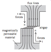
ill.1 Force components between two magnetically permeable teeth
: flux lines airgap magnetically permeable material forces
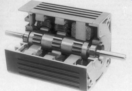
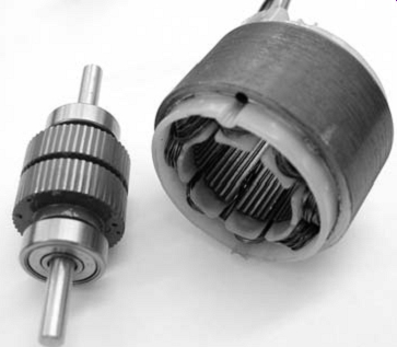
ill.2 Cutaway view of a three-stack variable-reluctance stepping
motor
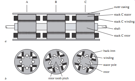
ill.3 a Cross-section of a three-stack variable-reluctance stepping
motor parallel to the shaft b Cross-sections of a three-stack variable-reluctance
stepping motor perpendicular to the shaft outer casing stack C stator stack
C winding shaft stack C rotor back-iron winding stator pole rotor -- rotor
tooth pitch
1.2 Multi-stack variable-reluctance stepping motors
In the variable-reluctance stepping motor the source of magnetic flux is current carrying windings placed on the stator teeth. These windings are excited in sequence to encourage alignment of successive sets of stator and rotor teeth, giving the motor its characteristic stepping action.
1.2.1 Principles of operation
The multi-stack variable-reluctance stepping motor is divided along its axial length into magnetically isolated sections ('stacks'), each of which can be excited by a separate winding ('phase'). In the cutaway view of Ill.2, For example, the motor has three stacks and three phases, but motors with up to seven stacks and phases have been manufactured.
Each stack includes a stator, held in position by the outer casing of the motor and carrying the motor windings, and a rotating element. The rotor elements are fabricated as a single unit, which is supported at each end of the machine by bearings and includes a projecting shaft for the connection of external loads, as shown in Ill.3a. Both stator and rotor are constructed from electrical steel, which is usually laminated so that magnetic fields within the motor can change rapidly without causing excessive eddy current losses. The stator of each stack has a number of poles - Ill.3b shows an example with four poles - and a part of the phase winding is wound around each pole to produce a radial magnetic field in the pole. Adjacent poles are wound in the opposite sense, so that the radial magnetic fields in adjacent poles are in opposite directions. The complete magnetic circuit for each stack is from one stator pole, across the airgap into the rotor, through the rotor, across the airgap into an adjacent pole, through this pole, returning to the original pole via a closing section, called the 'back-iron'. This magnetic circuit is repeated for each pair of poles, and therefore in the example of Ill.3b there are four main flux paths. The normal forces of attraction between the four sets of stator and rotor teeth cancel each other, so the resultant force between the rotor and stator arises only from the tangential forces.
The position of the rotor relative to the stator in a particular stack is accurately defined whenever the phase winding is excited. Positional accuracy is achieved by means of the equal numbers of teeth on the stator and rotor, which tend to align so as to reduce the reluctance of the stack magnetic circuit. In the position where the stator and rotor teeth are fully aligned the circuit reluctance is minimized and the magnetic flux in the stack is at its maximum value.
The stepping motor shown in Ill.3b has eight stator/rotor teeth and is in the position corresponding to excitation of stack A. Looking along the axial length of the motor the rotor teeth in each stack are aligned, whereas the stator teeth have different relative orientations between stacks, so in stacks B and C the stator and rotor teeth are partially misaligned. The effect of changing the excitation from stack A to stack B is to produce alignment of the stator and rotor teeth in stack B. This new alignment is made possible by a movement of the rotor in the clockwise direction; the motor moves one 'step' as a result of the excitation change. Another step in the clockwise direction can be produced by removing the excitation of stack B and exciting stack C. The final step of the sequence is to return the excitation to stack A. Again the stator and rotor teeth in stack A are fully aligned, except that the rotor has moved one rotor tooth pitch, which is the angle between adjacent rotor teeth defined in Ill.3b. Therefore in this three-stack motor three changes of excitation cause a rotor movement of three steps or one rotor tooth pitch. Continuous clockwise rotation can be produced by repeating the excitation sequence: A, B, C, A, B, C, A, ... . Alternatively anticlockwise rotation results from the sequence: A, C, B, A, C, B, A, ... . If bidirectional operation is required from a multi-stack motor it must have at least three stacks so that two distinct excitation sequences are available.
There is a simple relationship between the numbers of stator/rotor teeth, number of stacks and the step length for a multi-stack variable-reluctance motor. If the motor has N stacks (and phases) the basic excitation sequence consists of each stack being excited in turn, producing a total rotor movement of N steps. The same stack is excited at the beginning and end of the sequence and if the stator and rotor teeth are aligned in this stack the rotor has moved one tooth pitch. Since one tooth pitch is equal to (360/p) degree , where p is the number of rotor teeth, the distance moved for one change of excitation is:
step length = (360/Np) degree
The motor illustrated in Ill.3 has three stacks and eight rotor teeth, so the step length is 15 degree. For the multi-stack variable-reluctance stepping motor typical step lengths are in the range 2-15 degree.
Successful multi-stack designs are often produced with additional stacks, so that the user has a choice of step length; for example, a three-stack, 16 rotor tooth motor gives a step of 7.5 degree and by introducing an extra stack (together with reorientation of the other stacks) a 5.625 degree step is available. Although the use of higher stack numbers is a great convenience to the manufacturer, it must be remembered that more phase windings require more drive circuits, so the user has to pay a penalty in terms of drive circuit cost. Furthermore it can be shown that motors with higher stack numbers have no real performance advantages over a three-stack motor.
===
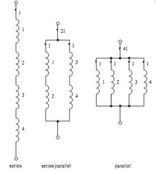
ill. 4 Interconnection of pole windings
Tbl.1 Effect of winding connection on ratings
Connection
Rated current
Resistance
Rated voltage
Power
Series
===
1.2.2 Aspects of design
Each pole of the multi-stack stepping motor is provided with a winding which produces a radial magnetic field in the pole when excited by a dc current. The performance of the stepping motor depends on the strength of this magnetic field; a high value of flux leads to a high torque retaining the motor at its step position. This relationship between torque and field strength receives more discussion in section 3, so for the present we need only consider how the pole magnetic field can be maximized.
In the position where rotor and stator teeth are fully aligned, as in stack A of Ill.3b, the reluctance of the main flux path is at its minimum value. For low values of current in the pole windings the flux density in the stator/rotor iron is small and the reluctance of these parts of the flux path is much less than the reluctance of the airgap between the stator and rotor teeth. As the winding current is increased, however, the flux density in the steel eventually reaches its saturation level. Further increases in winding current then produce a diminishing return in terms of improved flux level.
Another limitation on pole field strength arises from the heating effect of the winding currents. The power dissipated in the windings is proportional to the square of the current, so the temperature rise of the windings increases rapidly for higher currents. In most applications it’s the ability of the winding insulation to withstand a given temperature rise which limits the current to what is termed its 'rated' value. For a well designed variable-reluctance stepping motor the limitations on pole flux density and winding temperature rise are both effective: the stator/rotor iron reaches magnetic saturation at the rated winding current.
For the three-stack motor illustrated in Ill.3 there are four poles, and hence four pole windings, per stack. Since all four windings in one stack must be excited concurrently it’s common practice to interconnect the windings to form one phase.
The three alternative methods of connecting four windings are shown in Ill.4.
Although the rated pole winding current depends only on the acceptable temperature rise, the corresponding rated phase current also depends on the interconnection, as shown in Tbl.1. The rated phase voltage is the voltage which must be applied at the phase terminals to circulate the rated current in the windings. For the series connection the phase current is low and the voltage high compared to the parallel connection, but there is no difference in the power supplied to the phase. Most manufacturers produce a given design of stepping motor with a range of winding interconnections, so the user can select a low-voltage, high-current drive with the parallel connection or a high-voltage, low-current drive with the series connection.
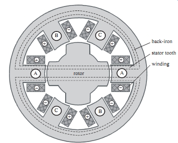
Ill.5 Cross-section of a single-stack variable-reluctance stepping motor
perpendicular to the shaft --back-iron stator tooth winding A, A rotor.
- - - flux paths for phase A excited
1.3 Single-stack variable-reluctance stepping motors
As its name implies, this motor is constructed as a single unit and therefore its cross section parallel to the shaft is similar to one stack of the motor illustrated in Ill.2 and 1.3. However, the cross-section perpendicular to the shaft, shown in Ill.5, reveals the differences between the single- and multi-stack types.
Considering the stator arrangement we see that the stator teeth extend from the stator/rotor airgap to the back-iron. Each tooth has a separate winding which produces a radial magnetic field when excited by a dc current. The motor of Ill.5 has six stator teeth and the windings on opposite teeth are connected together to form one phase.
There are therefore three phases in this machine, the minimum number required to produce rotation in either direction. Windings on opposite stator teeth are in opposing senses, so that the radial magnetic field in one tooth is directed towards the airgap whereas in the other tooth the field is directed away from the airgap. For one phase excited the main flux path is from one stator tooth, across the airgap into a rotor tooth, directly across the rotor to another rotor tooth/airgap/stator tooth combination and returning via the back-iron. However, it’s possible for a small proportion of the flux to 'leak' via unexcited stator teeth. These secondary flux paths produce mutual coupling between the phase windings of the single-stack stepping motor.
The most striking feature of the rotor is that it has a different number of teeth to the stator: the example of Ill.5 has four rotor teeth. With one phase excited only two of the rotor teeth carry the main flux, but note that the other pair of rotor teeth lie adjacent to the unexcited stator teeth. If the phase excitation is changed it’s this other pair of rotor teeth which align with the newly excited stator teeth. Ill.5 shows the rotor position with phase A excited, the rotor having adopted a position which minimizes the main flux path reluctance. If the excitation is now transferred to phase B the rotor takes a step in the anticlockwise direction and the opposite pair of rotor teeth are aligned with the phase B stator teeth. Excitation of phase C produces another anticlockwise step, so for continuous anticlockwise rotation the excitation sequence is A, B, C, A, B, C, A, ... . Similarly, clockwise rotation can be produced using the excitation sequence A, C, B, A, C, B, A, ... . It’s interesting to find that, in the motor illustrated, the rotor movement is in the opposite direction to the stepped rotation of the stator magnetic field.
The step length can be simply expressed in terms of the numbers of phases and rotor teeth. For an N-phase, motor excitation of each phase in sequence produces N steps of rotor motion and at the end of these N steps excitation returns to the original set of stator teeth. The rotor teeth are once again aligned with these stator teeth, except that the rotor has moved a rotor tooth pitch. For a machine with p rotor teeth the tooth pitch is (360/p) degree corresponding to a movement of N steps, so step length = (360/Np) degree
In the example of Ill.5 there are three phases and four rotor teeth, giving a step length of 30 degrees.
The number of stator teeth is restricted by the numbers of phases and rotor teeth.
Each phase is distributed over several stator teeth and, since there must be as many stator teeth directing flux towards the rotor as away from it, the number of stator teeth has to be an even multiple of the number of phases, e.g. in a three-phase motor there can be 6, 12, 18, 24, ... stator teeth. In addition, for satisfactory stepping action, the number of stator teeth must be near (but not equal) to the number of rotor teeth; for example, a three-phase, 15 degree step length motor is constructed with 8 rotor teeth and usually has 12 stator teeth.
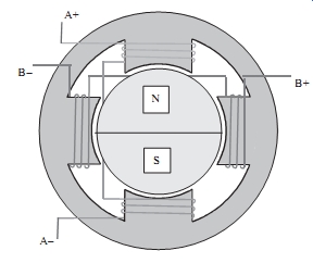
N S stator winding permanent magnet rotor ill.6 Side view and cross-sections of the hybrid stepping motor
Tbl.2 Relationship between winding current and pole field directions Winding Current direction Pole field direction Radially outward Radially inward A positive 3, 7 1, 5 A negative 1, 5 3, 7 B positive 4, 8 2, 6 B negative 2, 6 4, 8
1.4 Hybrid stepping motors
The hybrid stepping motor has a doubly salient structure, but the magnetic circuit is excited by a combination of windings and permanent magnet. Windings are placed on poles on the stator and a permanent magnet is mounted on the rotor. The main flux path for the magnet flux, shown in Ill.6, lies from the magnet N-pole, into a soft-iron end-cap, radially through the end-cap, across the airgap, through the stator poles of section X, axially along the stator back-iron, through the stator poles of section Y , across the airgap and back to the magnet S-pole via the end-cap.
There are typically eight stator poles, as in Ill.6, and each pole has between two and six teeth. The stator poles are also provided with windings, which are used to encourage or discourage the flow of magnet flux through certain poles according to the rotor position required. Two windings are provided and each winding (phase) is situated on four of the eight stator poles: winding A is placed on poles 1, 3, 5, 7 and winding B is on poles 2, 4, 6, 8. Successive poles of each phase are wound in the opposite sense, e.g. if winding A is excited by positive current the resultant magnetic field is directed radially outward in poles 3 and 7, but radially inward in poles 1 and 5. A similar scheme is used for phase B and the situation for the whole machine is summarized in the Tbl.2.
The influence of winding excitation on the magnet flux path can be understood by considering the example of winding A excited by positive current. The magnet flux in section X has to flow radially outwards and the excitation of A therefore results in most of the magnet flux flowing in poles 3 and 7. However, in section Y the situation is reversed, since the magnet flux must flow radially inwards and so is concentrated in poles 1 and 5.
Both the stator poles and rotor end-caps are toothed. For the motor illustrated in Ill.6 each of the eight poles has two teeth, giving a total of 16 stator teeth, and the rotor has 18 teeth. Note that the stator teeth in sections X and Y are fully aligned, whereas the rotor teeth are completely misaligned between the two sections. If the magnet flux is concentrated in certain poles because of the winding excitation then the rotor tends to align itself so that the airgap reluctance of the flux path is minimized. In the example of positive excitation of winding A the stator and rotor teeth are aligned under poles 3, 7 of section X and poles 1, 5 of section Y , as illustrated in Ill.6.
Continuous rotation of the motor is produced by sequential excitation of the phase windings. If the excitation of A is removed and B is excited with positive current then alignment of the stator and rotor teeth has to occur under poles 4, 8 of section X and poles 2, 6 of section Y . The rotor moves one step clockwise to attain the correct position. Clockwise rotation can be continued by exciting phase A then phase B with negative current. This sequence can be represented by: A+, B+, A-, B-, A+, B+,... . Alternatively anticlockwise rotation would result from the excitation sequence:
A+, B-, A-, B+, A+, B-, ... .
The length of each step can be simply related to the number of rotor teeth, p. A complete cycle of excitation for the hybrid motor consists of four states and produces four steps of rotor movement. The excitation state is the same before and after these four steps, so the alignment of stator/rotor teeth occurs under the same stator poles.
Therefore four steps correspond to a rotor movement of one tooth pitch of (360/p) degr. and for the hybrid motor step length = (90/p) degr.
The motor illustrated in Ill.6 has 18 rotor teeth and a step length of 5 degrees.
Hybrid motors are usually produced with smaller step lengths: the motor shown in Ill.7 has 50 rotor teeth and a step length of 1.8 degr.
A new innovation, aimed at improving torque production, is the fully pitched hybrid stepping motor, in which coils are wound around two poles.
Ill.7 A commercial hybrid stepping motor
1.5 Comparison of motor types
The system designer is faced with a choice between hybrid and variable-reluctance stepping motors and the decision is inevitably influenced by the application: it’s not possible to state categorically that one type is 'better' in all situations. Hybrid motors have a small step length (typically 1.8 degr.), which can be a great advantage when high resolution angular positioning is required. A survey of manufacturers' data revealed that the torque-producing capability for a given motor volume is greater in the hybrid than in the variable-reluctance motor, so the hybrid motor is a natural choice for applications requiring a small step length and high torque in a restricted working space. When the windings of the hybrid motor are unexcited the magnet flux produces a small 'detent torque', which retains the rotor at the step position. Although the detent torque is less than the motor torque with one or more windings fully excited, it can be a useful feature in applications where the rotor position must be preserved during a power failure.
Variable-reluctance motors have two important advantages when the load must be moved a considerable distance, e.g. several revolutions of the motor. First, typical step lengths (15 degrees ) are longer than in the hybrid type so fewer steps are required to move a given distance. A reduction in the number of steps implies fewer excitation changes and, as we shall see in Sections 5 and 6, it’s the speed with which excitation changes can take place that ultimately limits the time taken to move the required distance. A further advantage, highlighted is that the variable-reluctance stepping motor has a lower rotor mechanical inertia than the hybrid type, because there is no permanent-magnet on its rotor. In many cases the rotor inertia contributes a significant proportion of the total inertial load on the motor and a reduction in this inertia permits faster acceleration.
Apart from the two basic types of stepping motor discussed in this section, there are available several other devices capable of stepping action. The permanent-magnet stepping motor has a similar stator construction to the single-stack variable-reluctance type, but the rotor is not toothed and is composed of permanent-magnet material.
In the example of Ill.8 the rotor has two magnetic poles which align with two of the stator teeth according to the winding excitation. A change in excitation between the two windings produces a step of 90 degree.
The current polarity is important in the permanent-magnet motor. The rotor position illustrated is for positive current in winding A; a switch to positive current in winding B would produce a clockwise step, whereas negative excitation of B would give anticlockwise rotation. Recent advances in permanent-magnet materials have increased its versatility and there are many variants in diverse applications, including high-speed brushless dc drives.
At the opposite end of the size range is the electrohydraulic stepping motor, which is used in situations requiring very high torque. The motor is basically a closed-loop hydraulic control system which derives its input from a small conventional electrical stepping motor. Torque gains of several hundred are possible from the electrohydraulic stepping motor.
Ill.8 Permanent-magnet stepping motor