AMAZON multi-meters discounts AMAZON oscilloscope discounts
3. Types and Modeling of FACTS
As already mentioned, FACTS can be generally classified into two main groups based on the physical nature of the control action that they provide. One group of devices acts on reactance (reactive impedances), i.e., changing the power flow through the control of impedance, while the other uses static converters as voltage sources to inject or absorb power in the power system as appropriate.
The first group includes devices such as the Static VAr Compensator (SVC), the thyristor-controller series capacitor (TCSC), and the thyristor-controlled phase-shifting transformer (TCPST). SVC acts on the voltage magnitude, TCSC acts on the transmission line impedance, and TCPST acts on the transmission angle. It can be seen that each device controls one of the three parameters governing power transmission.
The static synchronous compensator (STATCOM), the static synchronous series compensator, (SSSC, sometimes it is referred to as solid-state series controller), the unified power flow controller (UPFC), and the interline power flow controller (IPFC) make up the second group of FACTS devices. These are converter-based FACTS controllers, with a synchronous voltage source, VSC, capable of generating internal reactive power, as well as exchanging real power with the network. Similarly to the SVC, the STATCOM acts on the voltage and the SSSC acts effectively on the transmission reactance. The UPFC can influence any of the three parameters, while the IPFC is able to provide real power transfer as well as reactive series compensation.
Major types of FACTS used in transmission systems around the world are listed in the following and described briefly. The most widely used, or distinctive in the way of design and/or operation, are discussed in separate subsections.
• SVC is a shunt-connected device consisting of a combination of power electronics controlled reactor and capacitor whose major role is to regulate the voltage at the point of connection by varying injected reactive power through modulation of susceptance.
• STATCOM is a shunt-connected solid-state synchronous condenser that controls either bus voltage magnitude or injected reactive power at the bus by varying its output current.
• SSSC is a series-connected solid-state synchronous condenser that controls either bus voltage magnitude or injected reactive power at one of the terminals of the series-connected transformer by varying its output current. (Similar to STATCOM but series connected.)
• TCSC is a series-connected device consisting of a series capacitor (which may also be thyristor controlled) paralleled by a thyristor-controlled reactor (TCR) whose major role is to ensure smooth variable series compensation through modulation of reactance and thus controls power transfer through the line. (Similar to SVC but series connected.)
• TCR is a shunt-connected thyristor-controlled reactor whose effective reactance is varied in a continuous manner by partial conduction of thyristor valve in order to regulate bus voltage magnitude.
• TCVR is a series-connected TCR whose effective reactance is varied in a continuous manner by partial conduction of thyristor valve in order to regulate voltage magnitude at one of the terminals of the series-connected transformer. (Similar to TCR but series connected.)
• TCPST is a series-connected TCR whose effective reactance is varied in a continuous manner by partial conduction of thyristor valve in order to regulate voltage phase angle at one of the terminals of the series-connected transformer (the main difference with respect to TCVR is in the way how the required voltage component is injected, i.e., in phase or at an angle with respect to line voltage).
• UPFC is a combination of a STATCOM and SSSC connected in a way that they share a common DC capacitor. It is able to control, simultaneously or selectively, the transmission line impedance, the bus voltage magnitude, and the real and reactive power flow through the line. Additionally, it can also provide independently controllable shunt reactive compensation.
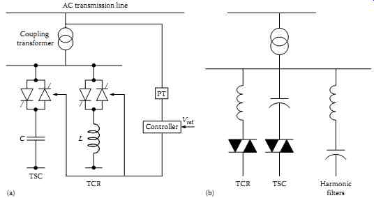
FIG. 3 Basic structures of the SVC: (a) design without harmonic filter
and (b) design with harmonic filter.
3.1 Static VAr Compensators
The SVC is a shunt-connected device based on application of conventional thyristors. It is in principle a shunt-connected variable reactor that has the ability to exchange reactive power with an AC power system in a smoothly controlled manner in order to regulate the voltage at the point of connection.
Assuming that the SVC is placed in the middle (typically) of the transmission line connecting two buses, the primary objective of the SVC is to maintain the voltage magnitude at the regulated point at a predetermined value. Voltage regulation is achieved by injecting the required amount of reactive power at the point of connection. In doing so, it indirectly increases the power transmission capability of the line.
Therefore, the relationship between the maximum power transmitted and the SVC action is indirect since the actual control over the transmitted power can be achieved mainly by the series line impedance and the angle difference between the two buses. FIG. 3 shows the basic structure of the SVC.
It can be seen from FIG. 3 that the SVC consists of two major parts that effectively control the injected (positive or negative) reactive power (Q). They are the thyristor-switched capacitor (TSC) and the TCR. Additionally, an integral part of an SVC may be a transformer if it is connected to a high-voltage bus. The SVC can be connected directly to the medium-voltage bus without a transformer. Finally, an SVC may, typically, contain a harmonic filter to ensure that there is no injection of unacceptably high harmonics in the network resulting from switching operation of thyristors. The coordinated switching between TSC and TCR controls the VAr output, which in turn maintains the bus voltage at the specified value. The basic SVC structure contains normally a number of TSCs and TCRs. A fixed-capacitor (FC) bank may also be included as a part of the SVC. There are more than 750 SVCs installed in the power networks around the world, and their ratings are generally problem dependant. SVC ratings from +45/−30 MVAr to +425/−125 MVAr have been reported in the literature.
3.1.1 SVC V-I Characteristic
FIG. 4 shows the SVC voltage-current characteristic at the regulated bus. It shows that the SVC regulates the bus voltage VT by either injecting reactive current in case of voltage drop or absorbing reactive current in case of voltage increase. The SVC V-I characteristic is limited in both the capacitive and the inductive region. In the capacitive region, if the capacitive current reaches the limit, the SVC behaves like an FC, i.e., it is no longer controllable. Thus, a further drop in the voltage causes a significant reduction in the generated reactive power as it is proportional to the voltage squared. This behavior is one of the major drawbacks of an SVC, since it cannot support the voltage adequately when it is strongly required. On the other hand, if the inductive current reaches the limit, the SVC becomes a fixed reactor.
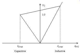
FIG. 4 The SVC V-I characteristic.
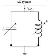
FIG. 5 The SVC in steady state.
3.1.2 Modeling of SVC for Steady-State Studies
Since the function of the SVC is to exchange reactive power with the AC power system at the point of connection, it will appear from the AC power system perspective as an equivalent to a parallel connection of shunt capacitor and a shunt reactor as shown in FIG. 5.
Based on the previous description, the SVC can be modeled in steady state as a variable-shunt susceptance (βSVC) as shown in FIG. 6.
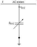
FIG. 6 The model of SVC in steady state.
The general form of power flow equations for the bus k is ....
In (1) and (2), the calculation of the real and reactive power involves the consideration of all the branches connected to bus k. In practice, because of the presence of the SVC variable shunt susceptance at bus k only, the change in the power flow equations for bus k including the SVC appears only when m = k as follows:....
....where G and B are the corresponding conductance and susceptance, of the network Ybus matrix, respectively.
3.1.3 Modeling of SVC for Transient Studies
A simplified mathematical model of the SVC for transient studies is briefly discussed below. The equivalent circuit of the SVC is shown in FIG. 7. The SVC is connected to the network bus ui through the coupling impedance (Rp, Lp). It comprises a parallel combination of a TCR and a TSC. It is assumed that the capacitor is switched on. The model does not take into consideration dynamics related to capacitor switching. Under dynamic conditions the reactance of the TCR changes, which is modeled by varying the factor bTCR that can take values between zero and one. The circuit also consists of resistance in series with the reactance in order to represent the losses of the TCR.
For the purposes of derivation of the mathematical model, per-unit system is adopted as specified by (5). iB and uB are the base current and voltage values, respectively, and ωB is the synchronous angular speed of the fundamental network voltage component. Mathematical descriptions are given in the rotating d-q reference frame. Under steady-state conditions, all the quantities in the model are constant values, which is suitable for the derivation of control algorithms:
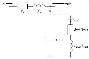
FIG. 7 Equivalent circuit of the SVC for transient studies.
Considering the above assumptions and instantaneous values of variables shown in FIG. 7, the state equations of the SVC in matrix format and using d-q coordinate system are given by ....
It should be noted that (6) represents the simplified mathematical model of the SVC, whereas the overall dynamic behavior of the device primarily depends on the applied control system. The SVC can operate in susceptance control mode, but the application of voltage control is more common. The output from the applied controller represents the value bTCRref. Modeling of an SVC for electromagnetic transient studies requires detailed representation of all SVC nonlinearities (semiconductor elements), as well as different control and protection functions.
3.2 Static Compensator
The STATCOM is also a shunt-connected device as SVC; however, it is a VSC-based device that maintains the bus voltage by injecting a variable AC current through a transformer and generates required reactive power at its terminal. Its operational principle allows the exchange of both real and reactive power with the power system if it is equipped with a DC energy storage. A STATCOM is in principle a static equivalent of the rotating synchronous condenser, which exchanges the reactive power with the system at much faster rate since there are no rotating parts (and such inertia) involved. The function of the STATCOM is the same as that of the SVC. It enables much more robust voltage support than the SVC. This increase in robustness comes with a higher price tag compared with the SVC of a similar size. Further comparison with the SVC shows that the STATCOM is smaller in physical size (about 30%-40% reduction in overall size of the SVC). The attainable response time and the bandwidth of the closed-voltage regulation loop of the STATCOM are also significantly better than those of the SVC. STATCOM can also incorporate suitable energy storage and thus facilitate real power exchange with the host AC system. This potential real power exchange capability provides a new tool for enhancing dynamic compensation, improving power system efficiency and, potentially, preventing power outages.
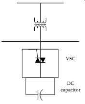
FIG. 8 Basic structures of STATCOM.
The basic structure of STATCOM is shown in FIG. 8. It consists of three-phase VSC, DC capacitor and transformer. The VSC uses self-commutated power electronic devices, GTO thyristors, or IGBTs to synthesize a voltage from a DC voltage source. Generally, a GTO thyristor is used for higher voltage applications and IGBT is for lower voltages. The capacitor on the DC side acts as a DC voltage source.
(Note: An SSSC is a series-connected FACTS device very similar to STATCOM, a part from its series connection. The SSSC is in fact a solid-state synchronous condenser that controls either bus voltage magnitude or injected reactive power at one of the terminals of the series-connected transformer. The injected voltage is perpendicular to the line current. The SSSC acts as a controllable voltage source whose voltage magnitude is controlled independently of the line current. By exchanging only reactive power with the system, the SSSC affects primarily the real power flow through a transmission line.)
3.2.1 STAT COM V-I Characteristic
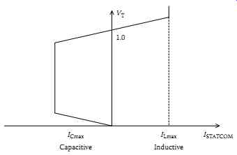
FIG. 9
FIG. 9 shows the V-I characteristic of STATCOM. It can be seen from the figure that even at very low voltage, unlike the SVC, the STATCOM can continue to operate with rated leading (or lagging) current and inject/absorb required reactive power. In contrast, the current injection of an SVC is proportional to terminal voltage and it reduces at lower voltages with voltage squared. STATCOM is therefore able to provide better voltage support than the SVC when the voltage becomes severely depressed.
3.2.2 Modeling of STAT COM for Steady-State Studies
Referring to its equivalence with a rotating synchronous condenser, STATCOM can be modeled as a conventional synchronous generator with zero real power output in series with the impedance of the connecting transformer (ZT). If higher flexibility in modeling is required, then it can be represented as a variable voltage source (E = E ∠θ = Ecos θ + jE sin θ) whose magnitude (E) and phase angle (θ) can be adjusted in each phase separately. In such a case, the limits should be set for voltage magnitude in accordance with the size of the DC capacitor, while the voltage phase angle can take any value between 0° and 360°.
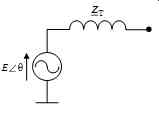
FIG. 10
Alternatively, STATCOM can be also represented as a variable current source for steady-state short-circuit calculations. Since its contribution to the system varies with its size and the connected bus voltage, the injected current has to be calculated carefully beforehand.
3.2.3 Modeling of STAT COM for Transient Studies
The equivalent circuit of the STATCOM model for transient studies is shown in FIG. 11. Sinusoidal voltage sources are connected to the network through the reactance of the coupling transformer. The circuit also consists of resistance in series with the reactance in order to represent the losses of the transformer. The current magnitude of the shunt-connected device depends on the difference between the system voltage and the adjustable output voltage of the converter. The DC circuit is represented by a current source connected to capacitor C.
The shunt connection of resistance Rc enables the representation of losses in the DC circuit.
Similarly as before, a per-unit system is adopted as specified by, iB and uB are the base values of current and voltage, respectively, and ωB is the synchronous angular speed of the fundamental network voltage component. Mathematical descriptions are also given in the rotating d-q reference frame:
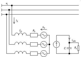
FIG. 11 Equivalent circuit of STATCOM.
Both components (d and q) of the converter output voltage depend on the DC voltage. A set of equations that defines these voltage components is given by, where kp is a coefficient that includes the transformer ratio, relates the DC and AC voltage, and takes into account converter type. Angle δp represents the phase shift of the converter output voltage from the reference position, and the control parameter (converter factor) mp can take any value between zero and one.
As can be observed from, both adjustable parameters of the converter output voltage, mp and δp, are used to determine the average switching function dpd in the direction of the d-axis and dpq in the direction of the q-axis:
DC circuit dynamics is described. The initial value of the DC voltage depends on the structure of the converter. It is determined in such a way that the device with mp = 1 operates in a capacitive area-the converter output voltage is higher than the network voltage.
As it can be observed, there are two adjustable parameters (mp, δp) and three state variables. Only two variables can be controlled independently. STATCOM does not have large energy storage capacity, thus only reactive power can be exchanged with the system in a steady state. The reactive current component can be controlled independently and the other free parameter is used for maintaining constant DC voltage across the DC capacitor.
An even more characteristic, or classical, mode of operation of STATCOM is when only one controllable parameter is used. The control factor mp is set to 1 and with the time-limited phase shift, δp, a certain amount of the energy can be absorbed or sent to the network. In this way, the magnitude of the DC voltage across the capacitor can be controlled, and consequently the magnitude of the converter output AC voltage or the reactive current component.
The mathematical model of the STATCOM with sinusoidal sources can be used to derive an appropriate control system. The outputs from the applied controller represent the values of the switching functions dpd and dpq. Mathematical modeling of STATCOM for electromagnetic transient studies requires detailed representation of the VSC and a relevant control system, where limits of controllable parameters would also need to be considered.
3.3 Thyristor-Controlled Series Capacitor
The TCSC is one of the series-connected FACTS devices based on thyristor valves. The primary function of a TCSC is to vary the line impedance through smooth modulation of reactance by appropriately switching off the thyristor valves. This ability to alter the series reactance of the transmission line offers a direct control over the transmitted power across the line. The TCSC therefore represents an excellent series compensator that is particularly useful for long transmission lines.
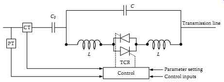
FIG. 12 The TCSC basic scheme.
FIG. 12 shows one of the basic TCSC designs. It consists of a series capacitor C in parallel with a TCR. The degree of series compensation provided to the line is controlled by the thyristor conduction period. The practical applications of TCSC may involve several cascading modules of this type.
The installation of the TCSCs started in early 1990s with three devices installed in the USA. The rating of the TCSC depends on the total power transfer across the transmission line that it is installed in. Recent examples of TCSC installations include a 107.5 MVAr device in Brazil in a network with total generation capacity of 62 GW and a 123 MVAr device in Sweden.
The ability of the TCSC to change the transmission line impedance can be used to achieve several tasks. In order to control the targeted parameters in the transmission line, such as the real power flow, the control law changes the reference signal of the TCSC controller in order to generate the desired value of the series compensation. Constant power (CP) and constant angle (CA) controls are two principle features of TCSC control. An example of TCSC application is shown in FIG. 13.
In case of CP control, the objective is to maintain the desired level of the real power flow in the TCSC compensated line (P23k) by changing the TCSC variable reactance. The desired real power flow level (P23ko) in line 2-3k is normally selected as the reference signal.
The CA type of control is applied when there are predefined transmission paths along the TCSC compensated line, e.g., as shown in FIG. 13 (line 2-3m). The control law in this case is to keep the total power transmitted across the parallel circuit (line 2-3m) constant. This is achieved by changing the TCSC series compensation such that any real power change in line 1-2 is absorbed. The reference signal in this case is P12o + P23ko. Assuming that the voltage magnitudes at bus 2 and bus 3 are regulated, that the transmission line resistance is negligible, and that the impedance of line 2-3m is fixed, the real power flow constancy in line 2-3m entails that the difference in voltage angles of bus 2 and bus 3 is constant.
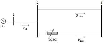
FIG. 13 The example of TCSC application.
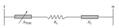
FIG. 14 The model of TCSC in steady state.
3.3.1 Modeling of TCSC for Steady-State Studies
The TCSC is modeled in the steady-state studies as a variable capacitive reactance in series with the impedance of the compensated transmission line as shown in FIG. 14.
Usually, the value of the XTCSC is only a fraction of the transmission line reactance XL. After adding the TCSC to a transmission line, the effective impedance of the line (neglecting the resistance) becomes ...
As far as the power flow equations are concerned, the inclusion of TCSC in the network also imposes some changes in power flow equations. FIG. 15 shows the lumped π-equivalent model of the transmission line used to illustrate the required changes.
The presence of the TCSC between bus k and bus m will introduce changes in the original Ybus matrix of the system, and these changes will appear in the power flow equations. Assuming that there are only two connections at each bus (bus k and bus m) as shown in FIG. 15, the injected powers at bus k
and bus m become ...
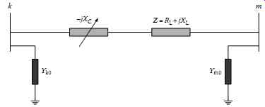
FIG. 15 The transmission line model including TCSC (−jXc).
3.3.2 Modeling of TCSC for Transient Studies
The equivalent circuit of the TCSC for development of mathematical model for transient studies is shown in FIG. 16. The line inductance is represented by Ls. The circuit also consists of series resistance Rs in order to represent line losses. The TCSC is a capacitive reactance compensator consisting of a capacitor bank (CFC) in parallel with a TCR in order to provide a smoothly variable series capacitive reactance.
The values for CFC and LTCR are chosen such that the factor bTCR can take any value between 0 (inductive TCSC reactance) and 1 (capacitive TCSC reactance), whereby values around the resonance point should be avoided. The voltage drop across the TCSC reactance due to line current is is denoted by uTCSC.
The per-unit system was adopted for the variables in the model. Again iB and uB are the base values for current and voltage, respectively, and ωB is the synchronous angular speed of the fundamental network voltage component.
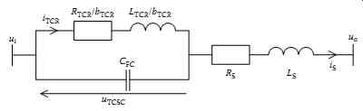
FIG. 16 Equivalent circuit of TCSC.
As in the case of the SVC modeling, the overall dynamic behavior of the TCSC primarily depends on the applied control system. As mentioned before, the TCSC can operate in a constant-current control mode or, in the case of parallel transmission paths, in a constant-angle control mode. The output from the controller is the reference value for the factor bTCR, i.e., bTCRref.
3.4 Thyristor-Controlled Voltage Regulator and Thyristor-Controlled Phase Shifting Transformer
The TCVR and TCPST are the other two types of FACTS devices that use thyristor valves as basic building components to perform fast switching, and therefore ensure smooth and continuous control of desired variable. They are very similar in design and therefore will be discussed together.
A TCVR is series-connected TCR whose effective reactance is varied in continuous manner by partial conduction of thyristor valve in order to regulate voltage magnitude at one of the terminals of the series-connected transformer. (Its function is very similar to that of TCR except that it is connected in series.) The role of TCPST on the other hand is to regulate the voltage phase angle at one of the terminals of the series-connected transformer. The main difference between TCVR and TCPST is in the way how the required voltage component is injected, i.e., in phase (TCVR) or at an angle (TCPST) with respect to line voltage, as illustrated in FIG. 17. The principle of operation of both, the TCVR and the TCPST, is based largely on the principles of operation of the classical on-load tap-changing transformer.
A significant disadvantage of these two devices is that they cannot generate nor absorb reactive power.
After they introduce desired changes in the bus voltage magnitudes and phase angels, it is left largely to the power system to handle the resulting change in the reactive power demand, so, a lack of reactive power support in the system in such cases might lead to a system security problem.
3.4.1 Modeling of TCVR and TCPST for Steady-State Studies
FIG. 18 shows a model of TCVR and TCPST in a transmission line where a represents the turns ratio and α represents the phase shift. The original line is between k1 and m; however, after inserting the TCVR (with a ≠ 0, α = 0) or TCPST (with a = 0, α ≠ 0), a new bus k is added to facilitate the demonstration of the change in the power flow equations.
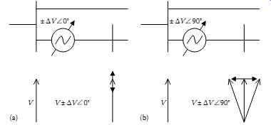
FIG. 17 (a) Voltage magnitude and (b) phase angle regulation by the
TCVR and TCPST, respectively.
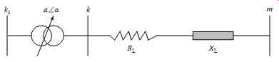
FIG. 18 A general model of TCVR and TCPST.
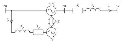
FIG. 19 Equivalent circuit of TCVR/TCPST.
3.4.2 Modeling of TCVR and TCPST for Transient Studies
The equivalent circuit of the TCVR/TCPST for transient studies is shown in FIG. 19. The transformer series branch inductance together with the line inductance is represented by Ls. The device is represented in the model by two controllable sinusoidal voltage sources with balanced real and reactive power exchange. Dynamics in the circuit between the two branches are neglected. The controllable parameter a or α of the series voltage source enables the main function of the device-voltage or power flow control. The zero exchange of the real and reactive power with the network is maintained by shunt-connected voltage source (ip, up). The circuit also contains a series resistance in order to account for the line losses. The inductance and the losses of the shunt branch are represented by Lp and Rp, respectively.
The adopted per-unit system for model development is given by ...
Voltage components, with consideration of controllable parameters, in the rotating d-q reference frame are described by ....
...where mi and mo are per-unit magnitudes of the input and output voltage, respectively, and the δi and δo ...
... are the respective phase angles. Considering the instantaneous variables shown in FIG. 19, the state equations of the TCVR/TCPST are given by...
The response times of the TCVR and TCPST power electronics are modeled using first-order blocks (37.38) with the time constant TTCVR and TTCPST, respectively. ....
The overall dynamic behavior of the TCVR or TCPST primarily depends on the applied control system as in the case of previously discussed FACTS devices. The output from the TCVR controller is the reference value aref and the output from the TCPST controller is the reference value αref.
3.5 Unified Power Flow Controller
The UPFC consists of two VSCs using GTO thyristors that operate from a common DC circuit consisting of a DC storage capacitor as illustrated in FIG. 20. It could be described as a device consisting of a parallel and a series branch. Each converter can independently generate or absorb reactive power.
This arrangement enables free flow of real power in either direction between the AC terminals of the two converters.
The function of the parallel converter is to supply or absorb the real power demanded by the series branch. This converter is connected to the AC terminal through a parallel-connected transformer. If required, it may also generate or absorb reactive power, which can provide independent parallel reactive compensation for the line. The second series-connected converter provides the main function of the UPFC by injecting an AC voltage with controllable magnitude and phase angle. The transmission line current flows through this voltage source resulting in a real and reactive power exchange with the AC system. A parallel branch provides the real power exchange at the AC terminal, while the reactive power exchange is generated internally by the converter.
3.5.1 Modeling of UPFC for Steady-State Studies
The UPFC equivalent circuit for steady-state modeling is shown in FIG. 21. The equivalent circuit consists of two ideal voltage sources:
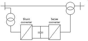
FIG. 20 Basic scheme of a UPFC.
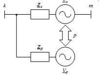
FIG. 21 UPFC steady state equivalent circuit.
Assuming a lossless converter operation, the UPFC neither absorbs nor injects real power from/to the AC system. The DC voltage remains constant. Hence, the real power supplied to the shunt converter must satisfy the real power demanded by the series converter.
3.5.2 Modeling of UPFC for Transient Studies
As mentioned above, the UPFC consists of a shunt- and series-connected VSC operating with a common DC circuit. Each of the two converters can independently generate or absorb reactive power. This structure enables free flow of the real power in either direction between the AC terminals of both converters. FIG. 22 shows an equivalent circuit of the UPFC.
On the AC side, the UPFC can be represented by sinusoidal voltage sources with a controllable magnitude and phase angle. The circuit also consists of series and shunt impedance representing coupling transformers. The influence of both converters connected in series and shunt to the DC system can be represented by two current sources in the common DC circuit connected to the capacitor C. Shunt connection of resistance Rc enables representation of losses in the DC circuit.
The derivations and mathematical descriptions are based on the transformation of a balanced three phase system into an orthogonal synchronously rotating coordinate system (d-q). The adopted per-unit system is given by …
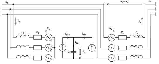
FIG. 22 Equivalent circuit of the UPFC using sinusoidal voltage sources.
Components of both converter output voltages depend on the DC voltage. Equations (47) and (48) can be written for the respective voltages where kp and ks are factors including a shunt and a series transformer ratio and relating the DC and AC voltage of each converter while taking into account converter type. The angles δp and δs represent the phase shift of each converter output voltage with respect to the reference position. The control factors mp for shunt converter and ms for series converter can take any value between 0 and 1.
Adjustable parameters of the converter output voltages mp, δp, ms, and δs can be used to determine the average switching functions dpd in the direction of the d-axis and dpq in the direction of the q-axis for the shunt converter, and similarly average switching functions dsd and dsq for the series converter.
The common balance equation for the real power using d-q components is given by ....
In the rotating reference frame, (d-q), the influence of both converters on the DC capacitor can be represented by a common DC current source: ....
It can be seen that there are five state variables and only four controllable parameters. The two current components of the series branch and the reactive current component of the shunt branch can be controlled independently. Indirectly, with the second free parameter of the shunt converter (the current d-component), the constant DC voltage across the common DC capacitor is maintained.
The UPFC can also operate in a variable DC voltage mode where the series branch still enables the exchange of the real power with the system, and the influence of the DC voltage variations can be compensated for with the proper setting of the series converter control factor ms.
The mathematical model of the UPFC with sinusoidal voltage sources may be used for the derivation of the appropriate control system. The outputs from the applied controller represent the values of average switching functions dpd and dpq for the shunt converter, and dsd and dsq for the series converter.
4. Areas of Applications of FACTS Devices in Power Systems
FACTS were originally developed to facilitate better control and operation of power transmission networks (and ultimately power systems as a whole) that started to face more and more constrains in their daily operation. Those constraints were further aggravated over the years by expansion restrictions imposed by environmental and social factors and by electricity market rules.
Modern FACTS devices are capable of performing a range of different tasks and functions that contribute to safe, secure, and economic operation of power systems. The contribution of FACTS devices to the enhancement of various attributes of power system can be broadly classified into four categories:
• Voltage stability and reactive power compensation
• Transfer capability and power flow control (or congestion management)
• Transient and small disturbance stability
• Reliability In the sequel, the contributions that FACTS devices make within each of those categories will be discussed separately. This does not mean, however, that the influence of any particular FACTS device is restricted to a single area while others remain unaffected. In reality, these devices usually affect several areas of power system operation simultaneously. Their "non-intended" contribution to system operation, i.e., the one that they were not originally designed for, may be either positive or negative, as reported in the literature.
4.1 Voltage Stability and Reactive Power Compensation
The TCSC and SVC were used in for the advanced VAr planning in a power system network in order to prevent voltage collapse following a contingency, while at the same time ensuring that the bus voltages remain within the statutory limits. The same devices were employed, to enhance voltage stability of the network. It was found that in addition to enhancing voltage stability, these devices greatly enlarged the region of small disturbance voltage stability. Enhanced voltage support by an SVC was also reported. Comparative study between a TCSC and SVC found that although both of them can support network voltages very well, the TCSC contributes to better power system voltage stability for a wide range of loading conditions. A UPFC and a STATCOM were used, respectively, to improve the voltage stability of the network. In addition to voltage stability improvement, the UPFC demonstrated excellent voltage control and series reactive power control capabilities.
In summary, series and shunt FACTS can be used effectively for voltage stability and reactive power compensation. They can greatly enlarge the region of voltage stability for a wide range of loading conditions and play an essential role in improving the voltage profile of the system.
4.2 Available Transfer Capability and Power Flow Control (Congestion Management)
The UPFC was used in for the enhancement of available transfer capability (ATC) and power flow control. It was found that the UPFC is a cost-effective solution for congestion management in a number of cases and that its advanced power flow control contributes to minimization of electricity generation cost. The issue of minimization of generation costs by optimal settings of parameters of various FACTS devices (TCSC, TCPST, UPFC, and SVC) was also addressed in.
The enhancement of ATC by a TCSC, a TCPST, or a combination of FACTS devices (SVCs and TCSCs) was also reported. It was found that the rating of FACTS devices plays an essential role in determining their contribution to congestion management and that the location of devices in the network should be carefully chosen as, depending on their location, they could have both positive and negative influence on system stability.
To summarize, a wide range of FACTS device can be effectively used for the enhancement of ATC and reduction in cost of electricity generation. Their rating and location in the power system though have to be carefully determined as they play important roles in their total impact on chosen network attributes.
4.3 Transient and Small Disturbance Stability
Apart from voltage regulation and stability improvement and congestion management, the FACTS devices have been also extensively used for the improvement of power system angular stability. The UPFC alone was used for the enhancement of system angular stability in and for damping of torsional oscillations in. For the similar purpose, damping of torsional oscillations, STATCOM was used in. The SVC, TCSC, STATCOM, and thyristor-controlled phase angle regulator (TCPAR)
were also used for the improvement of transient stability. It was demonstrated in that the SVC's contribution to transient stability is bigger than that of the TCSC's, though it depended more on its location than that was the case with a TCSC. Interestingly, a reasonably small degree of compensation (4%-5%) by TCSC is found to be sufficient for adequate damping of the inter-area power system oscillations. Many other derivatives of these basic types of FACTS devices have also been used for damping of power system oscillations. In most cases, conventional power system damping controllers (e.g., power system stabilizer) have been added in auxiliary control loops of FACTS to facilitate damping of electromechanical oscillations.
In all studies, without exception, it has been found that FACTS devices can greatly contribute to both small disturbance and transient power system angular stability. The contribution is particularly significant in damping of inter-area electromechanical modes that are very difficult to control by conventional, generator installed, damping controllers.
4.4 Reliability
In addition to the above more intuitive areas of FACTS' impact on system performance, a contribution of FACTS devices to power system reliability has been also verified. The impact of SVC, TCPAR, and UPFC on system reliability was addressed. It was found that this contribution is largely indirect through enhancing the system's transfer capability. Therefore, the contribution to system reliability can be considered as an additional benefit resulting from application of FACTS device to address some of the previously mentioned concerns (i.e., congestion management, voltage stability and control, angular stability.)
5. Rating of FACTS Devices
The rating of FACTS is strongly influenced by their intended function and by the way in which they are connected to the network, i.e., in series or in shunt.
The SVC, for example, is a shunt-connected device with two operating regions, inductive and capacitive.
For the inductive mode, the rating should be chosen in order to protect the bus voltage from temporary overvoltages. On the other hand, in the capacitive mode of operation, it should be able to inject the required reactive power in order to maintain the bus voltage within statutory limits during the rated power flow over the transmission line.
The TCSC is installed in series with the transmission line of interest. It entails that the TCSC, in terms of insulation, must be able to withstand the full line current over the transmission line and the line voltage at its terminals. This, of course, affects its cost. The TCSC rating is generally determined as a percentage of the total MVAr losses over the compensated transmission line at the full line current. For instance, if the full line current is 2000 A and the voltage drop is 60 kV, the total MVAr losses will be 120 MVAr. Assuming that the TCSC should compensate up to 25% of the total transmission line reactance, the TCSC rating will be 120 × 0.25 = 30 MVAr. The usual range of TCSC reactance (XTCSC) variation with respect to compensated transmission line reactance (XL) is from 0.8XL to 0.2XL.
The TCVR and TCPST are also installed in series with the transmission line; however, unlike the TCSC, they exchange the full real and reactive power flows with the transmission line. This makes their required rating high compared to other devices. The TCVR turns ratio is typically chosen to be between 0.9 and 1.1 p.u., while the phase shift provided by the TCPST is usually in the range of ±5°. A conventional phase shifter can vary angle approximately within ±30° in discrete steps of about 1° or 2°.
6. Cost of FACTS Devices
The previous sections described FACTS devices at some detail and showed that these versatile and technically advanced systems can offer huge advantages to the operation and control of electric power systems.
In spite of their unquestionably high technical performance and control abilities, the number of real-life applications is still not as high as one might expect based on potential advantages that they can offer to power systems. One of the major drawbacks of this rather slow uptake is their very high price.
The following subsections address the cost of FACTS device in a bit more detail.
6.1 Cost Structure
The cost of FACTS devices has two main components: initial installation cost and operation and maintenance cost. The initial installation cost includes the cost of device plus delivery and installation charges, professional fees, and sales tax. The total installation cost is usually expressed as a function of rated electrical capacity of FACTS device. The other cost component, operation, and maintenance cost is incurred over the lifetime of the system. Operating costs include maintenance and service, insurance, and any applicable taxes. A rule of thumb estimate for annual operating expenses is 5%-10% of the initial system cost. A typical initial installation cost structure for FACTS device can be laid out as follows: hardware, 55%; engineering and project management, 15%; civil works, 12%; installation, 10%; freight and insurance, 4%; and commissioning, 4%.
6.2 Price Guideline
The cost of a FACTS installation depends on many factors, such as power rating, type of device, system voltage, system requirement, environmental conditions, regulatory requirement, etc. Due to the variety of options available for optimum design, it is impossible to give a generic cost figure for a FACTS installation. The approximate prices of SVC and a range of VSC-based devices are shown in TBL. 1.
Similarly rough guidelines are provided in TBL. 2 [66] for the purchase and installation cost of a medium-size (between 100 and 500 kVA) devices.
The costs of SVC and STATCOM are shown as exponentially decreasing functions of the rating of device with and without installation costs. The extrapolated values from those curves are summarized in TBL. 3.
Based on the above figures one can only conclude that the price of FACTS devices varies within a wide range and that it is very difficult to give a generic cost for any of them.
7. Conclusion
The FACTS devices are undoubtedly versatile and technically advanced systems that can offer huge advantages to operation and control of electric power systems. Their ability to control quickly and efficiently one or more power system parameters will particularly be required in the future power networks characterized by proliferation of renewable, often stochastic or intermittent, generation built (typically) in the areas with limited power transfer infrastructure (leading to creation of power transfer bottlenecks), by market-driven demand for increased cross-border power transfers (beyond existing typical maximum of 10%) and ever-increasing demands for higher quality and security of electricity supply and participation of distributed demand and storage in peak shaving.
The major issue that hampered their proliferation in the past was their high cost. In the foreseeable future it is expected that the cost of FACTS devices will continue to fall, chiefly due to reduction in cost of power electronic components, while their effectiveness will further improve. Envisaged reduction in cost will certainly further contribute to their competitiveness. More importantly, since FACTS devices generally contribute to the enhancement of several electrical power network functions simultaneously, the benefits resulting from their installation will also start to be assessed more comprehensively, i.e., taking into account several contributions at the same time, and it will be easy to prove that they are cost-effective options for facilitating flexible electric power networks of the future.