AMAZON multi-meters discounts AMAZON oscilloscope discounts
Single-phase rectifier circuits have been used since the advent of vacuum-tube diodes. When vacuum tubes were first introduced to control voltage and current, they required a variety of dc power supplies. Since the dc power supplies originated from ac voltage, vacuum-tube diode rectifiers were used to convert ac voltage to dc voltage. When solid-state devices were developed, the first uses for solid-state diodes were to provide rectification of ac voltages to provide the necessary dc voltages.
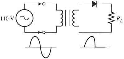
Fig. 1 (below) shows an example of a power supply that uses a single solid-state diode rectifier. From this figure notice that this type of power supply uses a transformer to increase or decrease the voltage from the 110 volt ac supply voltage. When ac voltage is applied to the transformer primary circuit, its secondary will supply voltage to the diode rectifier. A resistor is shown to indicate a typical load.

Above: Fig. 7-1 Electrical circuit diagram of a single-diode rectifier power
supply. The waveforms show ac voltage supply and halfwave dc at the load resistor.
The diagram also shows a typical waveform for the input voltage and the waveform for the rectified voltage. One would see the full sine wave if one placed an oscilloscope across the two transformer leads that are the input of the diode rectifier, and one would notice the single half-wave if one placed the oscilloscope leads across the load resistor. Notice that since only one diode is used, the half-wave in the output waveform occurs when the ac input voltage is positive between 0° and 180°. No output voltage will be supplied during the point from 180° to 360° where the ac voltage is negative. (Note: The ac line voltage in North America may be generated from any value between 110-125 volts, and the amount of voltage available at the electrical outlet may be slightly higher or lower at various times of the day. To avoid confusion, the value 120 volts will be used for discussion of all ac line voltage on this web site.)
It's important to be able to calculate the amount of dc average voltage (dc half-wave) that will be available at the load. The average dc voltage read with a dc voltmeter is called the dc voltage for the rectifier. The formula for the dc average voltage for a single-diode rectifier is:
V dc av = VP/π
where π = 3.1416.
This formula can be converted by dividing Vp by / π so that the new formula is:
V dc av = 0.318 VP
The peak voltage can be calculated from the root-mean-square (rms) value of the ac supply voltage. Peak voltage is the value of voltage that is measured from the 0 volt line to the peak of the sine wave and it must be measured with an oscilloscope or with a peak-reading voltmeter. The rms voltage is the voltage one would read if one were using an ac voltmeter. For example, the 120 volts one would find in a U.S. or Canadian wall receptacle is actually 120 volts rms. The formula for calculating peak voltage from rms is:
peak volts = rms volts x 1.414
or:
V p = V rms x 1.414
It's also important to remember that the diode in this circuit will drop approximately 0.7 volt since it's a silicon diode. (It should be noted that in larger-power diodes, the drop may be as much as 2 volts.) This voltage drop would be calculated if the information one is determining needs to be more precise. The equation for V dc av with the voltage drop for the diode is:
V dc av = (V P - 0.7)/π
Exercise
Calculate the V dc av voltage for a single-diode half-wave rectifier that has an input voltage of 120 volts ac rms (including the 0.7 volt drop for the diode).
Solution
The first step of this calculation involves finding the peak ac voltage from the rms voltage.
From the equation
V P = V rms X 1.414
110V rms X 1.414 = 169.68 V dc peak
From the equation
V dc av = (V P - 0.7)/π
(169.68V P - 0.7)/π
= 54.01 V dc av

