AMAZON multi-meters discounts AMAZON oscilloscope discounts
The buck converter circuit is the basis for several other similar circuits called forward converters. The buck converter circuit and the input and output voltages for this circuit are shown in Fig. 1. This circuit would be connected directly after the power transformer. From the diagram notice that this circuit is fairly simple in that it consists of a transistor, inductor, diode, and capacitor. When the transistor is turned on, power will flow directly to the output terminals. This voltage must also pass through the inductor, which will cause current to build up in it in much the same way that a capacitor charges. When the transistor is switched off, the stored current in the inductor will cause the diode to become forward bias, which will let it freewheel and allow the current to be delivered to the load that is connected to the output terminals.
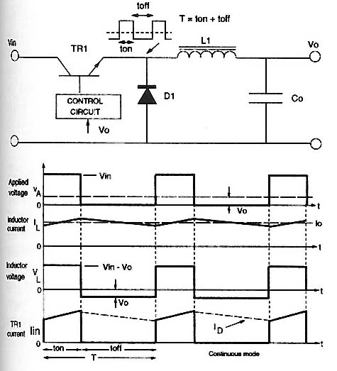
Above: Fig. 1: Schematic and waveforms for a buck converter circuitry
for a switch-mode power supply.
The waveforms at the bottom of the diagram show the square wave of the input voltage in the top line. The waveform on the bottom line shows the effects of the inductor putting the stored current back into the circuit to the load. This current is shown as the dashed line that occurs during the square wave off-cycle. This type of circuit is called a step-down buck converter because the output voltage will always be smaller than the input. Voltage regulation for this circuit is controlled by duty cycle. If the off-time for the duty cycle is lengthened, the average voltage to the output will be lower, and if the off-time for the duty cycle is shortened, the average power will increase.