AMAZON multi-meters discounts AMAZON oscilloscope discounts
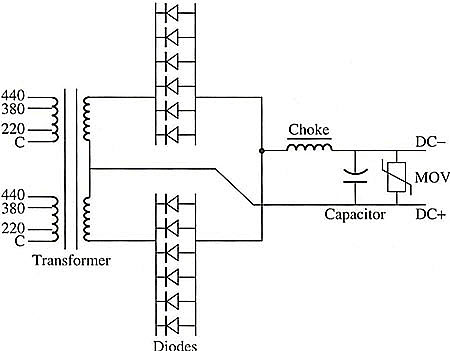
Another application of industrial equipment that uses a large power supply is a welding system. This welding system is specifically designed for dc arc welding, meaning it will get its supply power from an ac power source that must be converted to dc voltage. Fig. 1 shows the diagram of the power supply for this welding system. Notice that the supply voltage in this system is single-phase (two wires) ac voltage, which can be 220, 380, or 440 volts. The main transformer has multiple taps to accommodate each of these supply voltages. All the welding tech. needs to do when supply power is connected during the installation process is to measure the supply voltage and connect the lines to the appropriate terminals on the main transformer. The taps on the transformer are clearly identified so that the connection can be made for each different type of voltage.

Above: Fig. 1: Electrical diagram of the power supply for a six dc arc-welding
system. Notice that this power supply uses six diodes in each section
of a center-tapped transformer full-wave bridge rectifier. The diodes
are connected in parallel to supply larger currents.
The main transformer consists of two single-phase primary windings that are connected in parallel. This means that each of the primary windings will receive the same voltage. The secondary windings of this transformer and the diodes are connected like a center-tapped full-wave bridge rectifier. The main difference in this circuit is that each section of the rectifier uses six diodes that are connected in parallel so that the power supply can provide current that is larger than the rating of each individual diode. In fact the current rating of this power supply will be 12 times the size of each individual diode because this configuration of rectifier uses a center-tap transformer. This means that the current rating of each diode can be 100 A, and the power supply can provide over 1000 A. This type of circuit was very popular in the 1980s when the size of diodes was restricted to 100-150 A. Today larger diodes are available to provide current in excess of 1500 A.
The output section of this power supply has a filter with a choke (inductor) that is connected in series with the dc negative line, and a capacitor that is connected in parallel across the positive and negative dc lines. A metal-oxide varistor is connected in parallel with the capacitor and the load. Realize that the MOV is in the circuit to protect against over-voltage conditions. The MOV would cause a fuse in the transformer secondary to open anytime the voltage exceeds its rating.

