AMAZON multi-meters discounts AMAZON oscilloscope discounts
Most industrial power supplies require the dc output voltage to have some type of regulation to keep the output voltage level constant when the input voltage fluctuates. The ac voltage that supplies power to industry today will fluctuate up to 10% of the supply voltage specification. This means that in the hottest days of the summer it may not be uncommon for the three-phase 208 volts that is supplied to a machine to drop below 200 volts. When this occurs, the dc output voltage of all of the rectifier circuits will also drop. When the dc voltage drops, the circuit may become unreliable, so a zener diode is generally used in the output section of the power supply to provide voltage regulation. Fig. 1 shows a circuit with the zener diode connected in parallel with the load.
The zener diode must be rated for the same voltage the dc load requires. For example, if the dc load needs 20 volts dc, the zener will be rated for 20 volts. The operation of the zener diode in the regulation part of the circuit can easily be explained using the diagram in Fig. 1. In this circuit notice that the zener diode is connected in parallel with the load resistor and it's connected in reverse bias with the power supply. In normal conditions, the output voltage from the rectifier is 15% to 20% larger than the zener level. The zener diode will go into conduction when the voltage reaches or exceeds its rating. In the circuit in the diagram, the zener diode is rated for 30 volts dc, and the full-wave bridge voltage that is supplied to it's 35 volts. Since the 35 volts exceeds the zener rating, the zener diode will go into conduction and create a voltage drop across its terminals of exactly 30 volts. Since the load resistor is connected in parallel with the zener, the 30 volts across the zener terminals will be the same voltage supplied to the load resistor. Anytime the voltage is less than the zener rating, the zener will present high resistance and have no effect on the circuit.
If the ac voltage that supplies the diode section of the rectifier drops 2% or 3%, the peak half-wave dc voltage at the output will drop 1-2 volts. This means that the original 35 volts will become 33 or 34 volts. Since this voltage still remains larger than the zener diode rating, the zener diode will continue to stay in conduction and provide the 30 volt drop and continue to supply 30 volts to the load. As can be seen, the incoming ac voltage will need to drop more than 10% to cause the dc half-wave voltage to become lower than the zener diode rating, and cause it to stop regulating.
It's important to understand that as the dc half-wave voltage becomes larger, the zener must shunt more current. The term shunt means that the zener diode will provide a parallel path for this excess voltage and current so that the load resistor will always be supplied with a constant 30 volts. Zener diodes come in a variety of voltage and current ratings for all types of industrial power supplies up to several hundred volts.
If an oscilloscope is used to view the waveforms in a power supply, one will note that the voltage from the terminals of the rectifier will be complete full-wave rectification like the waveform shown in Fig. 1b. The waveform that would be observed at the load is shown in Fig. 1c and it shows the top parts of the rectified full-wave as missing because the zener diode shunted the excess voltage so that the load would see the regulated 30 volts.
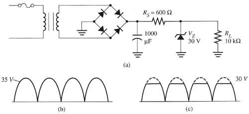
Above: Fig. 1 (a) Electronic schematic that shows
a zener diode connected to the output side of the rectifier circuit so
that it can supply a regulated voltage to the load. (b) The waveform of
full-wave rectification voltage at the output of the rectifier. (c) The
waveform of the regulated voltage measured across the load after it passes
the zener diode.

