AMAZON multi-meters discounts AMAZON oscilloscope discounts
While many different terms are used to describe electrons and their behavior, you will encounter a core set, common to all electronics, in your repair work. Some deal with electrical units, some with parts and their characteristics, some with circuit concepts, and others with hip tech slang. (Okay, you can stop laughing now!) Others describe frequently employed circuits used as the building blocks of many products.
Getting familiar with these terms is crucial to your understanding the rest of this guide, so let's look them over before moving on to Section 6.
We'll touch briefly on the most vital terms here; for more, and greater detail, check out the Glossary at the back of the guide. You'd be doing yourself a favor to read the entire Glossary, rather than just using it for reference. Otherwise, you'll find yourself flipping pages back and forth a great deal as you read on. And believe me, you don't want to miss the definition of magic smoke.
Electrical Concepts
Being an intangible essence, electrical energy must be described indirectly by its properties. It possesses quite a number of them, and many famous scientists have teased them out with clever observations throughout the last few centuries.
Experiments with electricity have gone on since the 1700s, when Ben Franklin played with lightning and miraculously lived to write about it-talk about conducting an experiment! Volta and Ampere built batteries and watched how their mysterious output affected wires, compasses and frogs' legs. Ohm quantified electrical resistance, and many others contributed crucial insights into this amazing natural phenomenon's seemingly bizarre behavior.
Perhaps the most valuable discovery was that electricity is a two-quantity form of energy. Its total power, or ability to do something like light a lamp, spin a motor or push a speaker cone, has two parts: how much of it there is, and how strongly it pushes.
The ampere, or amp for short, is a measure of how much electrical current is moving through a circuit. Interestingly, actual electrons don't travel very fast at all and are not what moves through the wires, semiconductors and other parts of a device. Rather, their charge state gets transferred from atom to atom, raising the energy level of each one's own electrons, thus passing the current along. Imagine throwing a stone into a pond and watching the resulting wave. The wave propagates outward, but do the atoms of water at the center, where you threw the rock, actually wind up at the edge of the pond? No; they hardly move at all. They just push against the atoms next to them, transferring the stone's mechanical energy from one to the next.
The amount of current, or number of amperes moving through a circuit, has nothing to do with how hard they push, just as the amount of water in a hose has no relation to how much pressure is behind it. The pressure is what we call volts, a measure of how high each electron's energy state rises. Volts tell you how much pressure is pushing the amps through the circuit. In fact, voltage is sometimes referred to as electrical pressure, or electromotive force. It’s unrelated to how much electricity there is, just as the pressure in a hose doesn't tell you how much water is present. Volts propel current through the circuit. After all, without pressure, the water will just sit in the hose, going nowhere, right? The hose isn't infinitely large, of course, and doesn't permit a perfectly free flow.
Friction opposes and limits the motion. When the "hose" is a wire, that means it has resistance. Resistance is basically friction at the atomic level, and the energy lost to it from electrons and atoms rubbing against each other is converted to heat. The term for resistance is ohms, after the man who deduced the relationship between current, voltage and resistance. We call his crucial insight into electrical behavior Ohm's Law. If you hate math and don't want to memorize formulas, at least get the hang of this rather simple one; it's the most important, useful relation in all of the electrical arts, and grasping its essence will greatly aid your troubleshooting. See Ohm's Law in the Glossary.
When you put voltage and current together, you get the total picture of the power of the power, so to speak. We call that watts, and it describes how much work the energy can do. Determining watts is simple: just multiply the volts times the amps. So, 25 volts at 4 amps equals 100 watts, and so does 5 volts at 20 amps. Either arrangement could be converted to the same amount of mechanical work or produce the same light or heat.
As it comes from a battery, electricity is in the form of direct current, meaning it moves only in one direction. The side of the battery with excess electron charge is called negative, while the side with a lack of it’s called positive. Thus, by definition, current passes from negative to positive as it attempts to correct the imbalance of charges. Why not the other way around? I suppose we could have named either terminal whatever we wanted, but those names were known in Franklin's time and have persisted. And they relate to our modern model of the atom, with the electron's negative charges, so I doubt anyone's going to change them.
Flipping the polarity, or direction of current, back and forth turns out to create many useful effects, from easing long-distance power transmission to the magic of radio signal propagation. That's alternating current, or AC, and you'll see it in just about everything. How fast you flip it’s the frequency, specified in hertz (Hz). The old term was cycles per second. It's nice to have one word for it, don't you think? I wonder why we don't have one for speed, instead of miles per hour. We should call them glorphs. "I'm sorry, sir, you were going 45 glorphs in the 25 glorph zone. License and registration, please." When you put two conductive plates in proximity to each other and apply voltage, they talk to one another in a peculiar way. A charge builds up on either side of the insulator between them, and that charge can be taken out and turned back into current.
We call that phenomenon capacitance, and the parts doing the job are capacitors.
Essentially, capacitors act like little storage wells of electricity.
Electricity and magnetism are very related things, and they interact with each other.
In fact, one can be turned into the other quite easily, by passing a current through a coil of wire or by moving a magnet in a coil of wire. Passing current through the coil generates a magnetic field, and moving a magnet through a coil generates current.
When a coil generates a magnetic field and then the direction of applied current reverses, the field collapses on the coil and generates current in it in the opposite direction to the current that created the field. Essentially, the coil stores some energy in the magnetic field and then puts it back into the circuit, but going the other way.
That behavior is called inductance, and it has all kinds of very important implications in alternating-current circuits. A coil used that way is an inductor. Two different-sized coils wound on a common metal core can be used to transform one combination of current and voltage into another, with the magnetic field created by one generating current in the other. That's a transformer.
The effect capacitors and inductors have on AC currents is called reactance, and the combination of capacitive reactance, inductive reactance and resistance is known as impedance. That's an especially apt term because it quantifies the amount the circuit impedes the passage of the AC current going through it. Though it doesn't behave exactly like resistance-it's frequency-dependent, for instance-impedance is similar to resistance for AC current and is specified in ohms, just like pure resistance.
Circuit Concepts
When you wire up a bunch of parts such that current can pass through them and return to its point of origin, you create a circuit. The circuit concept is central to all electronics, and virtually every device that does anything is part of one. So, naturally, lots of terms are used to describe the functions and characteristics of circuits and the signals that flow through them.
When two or more circuit elements (components) are wired so that the current has to pass through one of them to reach the other, they're in series. Examples of things in series are fuses and switches; nothing can reach the rest of the circuit without passing through them first. It makes sense that the current through each element would have to be the same, since the amount of electricity reaching the return end of the power source has to equal what left it in the first place. Indeed, that's true. The current that passes through each element of a series circuit is always equal.
Still, energy has to be used in order for the part to do anything, so something has to give. What changes is the voltage. Each element drops the voltage, essentially using up some of the electrical pressure, until the total drop equals the applied voltage. The elements don't necessarily all drop the same amount of voltage, though. As Ohm so cleverly figured out, the amount dropped is proportional to the element's resistance. If one element has 20 percent of the total resistance of the circuit, it drops 20 percent of the voltage. Another element that has 10 percent of the total resistance drops 10 percent of the voltage, and so on. They'll always add up to 100 percent, right? Thus, all the voltage will be dropped by the time the other side of the power source is reached.
When circuit elements are wired so that multiple components are connected across the power source's two terminals, they are connected in parallel. In this case, each one gets the full voltage because nothing is in the way to drop some of it. The amount of current passing through each part is proportional to its resistance, regardless of the other parts also connected. Basically, they have no reason to notice each other. If you measure the total current passing through a parallel circuit, it'll add up to all the currents going through each leg, or element. A parallel circuit's conditions are exactly opposite to those of a series circuit: the voltage is constant but the current varies.
Circuits with a path from one end of the power source to the other are said to be complete, or closed. That's the normal operating state; unless a circuit is closed, nothing flows and nothing happens. When there's a break in the path, perhaps from a switch in the "off" position or a blown fuse, energy flow stops and the circuit is open. Any failed component no longer capable of passing current is considered open as well.
A condition causing part or all of a circuit to be bypassed, so that current passes straight to the other end of the power source, is called a short circuit, and the parts causing the detour are said to be shorted. Certain types of components, especially semiconductors, often short when they fail.
Although the generation and transport system bringing power into your home provides AC, electronics really can't use the stuff. Just as you couldn't drink from a cup swinging back and forth, circuits can't take AC power and amplify or process signals with it; the changes in the power itself would show up in the output. What's needed is a nice, steady cup from which to sip. In other words, smooth DC.
Once AC is rectified, or converted into one polarity, it's still a series of waves of power going up and down. To smooth it into a steady voltage, some kind of reservoir needs to store some of it, so that as the wave strength approaches zero between waves, the stored energy can fill in and raise the voltage back up. That reservoir is a filter capacitor. It's just a big capacitor that can store enough energy to do the job, momentarily emptying itself to power the rest of the circuit until the next power wave fills it back up again.
As circuits turn on and off and their signals rise and fall, their varying use of current can pull the voltage level feeding them up and down, causing corruption of the desired signal. Smaller filters called bypass capacitors, placed close to the part of the circuit pulling current, store some energy to fill in the gaps, just like the big guns do. The only difference between a filter capacitor and a bypass capacitor is its size. Generally, big ones in power supplies are called filter caps, and little ones in signal processing stages are called bypass caps. Bypass capacitors are also used to provide a low-impedance AC path to ground in parts of amplifiers where that's needed, without shorting out the DC on the same connection.
The circuitry in an electronic product is not just a huge mishmash of components.
It’s organized into sections and, within those, stages. Each stage performs one function of whatever process is required for the device to do its job. A stage might be an audio preamplifier (a low-level amplifier), a tone control, a video display driver, a demodulator (something that extracts information from a signal), a position detector for a motor, and so on. At the heart of each stage are one or more active elements. These are the parts that actually do the work and are generally defined as being capable of providing gain, which you'll read about in just a few paragraphs. Supporting the active elements are passive components like resistors, capacitors and inductors. Those can alter a signal, but they can't amplify it. Without them, though, the active elements can't do their jobs.
Stages feed signals to other stages, until the device finally produces whatever output is desired. The components passing the signal from one stage to the next are called coupling elements, and are usually capacitors, resistors or transformers.
Signal Concepts
Signals are voltages varying in strength, or amplitude, to convey some kind of information.
Analog signals vary the voltage in a pattern resembling the information itself. For instance, the output of an audio amplifier looks like a graph of the original pressure waves of sound in the air that struck the microphone. A video circuit's signal has varying voltages representing the brightness of each dot on the screen, with a rather complex method of conveying color information and synchronizing the spots to the correct place in the picture. Its graph doesn't look like an image, but it's still an analog signal, with fine voltage gradations portraying the changing picture information.
The graph of a signal is called its waveform. Every time the waveform repeats, that's one cycle. The number of cycles occurring in 1 second is the waveform's frequency, and the amount of time each cycle takes is its period. Because the voltage varies over time, it’s a mathematical function, meaning that its lines can't cross over themselves. Graphed from left to right, as they are on an oscilloscope, the level at each successive moment is to the right of the preceding moment's portrayal.
The purest, most basic waveform is the sine wave ( FIG. 1). It’s the building block from which all other waves can be created, and it has no harmonics, or energy at frequencies that are multiples of the wave's frequency. A sine wave sounds like a pure tone, with no characteristics suggesting any particular musical instrument or tone color. In fact, no non-electronic musical instrument produces sine waves, though some registers on the flute come close. A tuning fork comes closer.
When a signal rapidly switches between all the way on and all the way off, it assumes a square shape and is called, appropriately, a square wave ( FIG. 2). Close enough examination will reveal that the on/off transitions aren't entirely vertical, because it takes time for the state to change. Thus no square wave is truly square. The time it takes the transition to rise from 10 percent to 90 percent of its final state is the rise time. Going back down, it's the fall time.
The percentage of time spent in the "on" state, compared to the "off" state, is called the duty cycle and can be altered to represent information or control a motor or a voltage regulator, using a technique called pulse-width modulation, or PWM. Unlike sine waves, square waves contain harmonic energy. They include odd harmonics, but not even ones.
That is, there is energy at three, five and seven times the frequency, but not at two, four and six times.
A signal used in applications requiring something to move and then quickly snap back is the sawtooth wave, so named for its obvious resemblance to its namesake ( FIG. 3). Oscilloscopes and CRT TVs use sawtooth waves to sweep the beam across the screen and then have it rapidly return. Other circuits, including servos (motor position controllers) in video tape recorders, use sawtooth waves too.
Sawtooth waves include both odd and even harmonic energy.
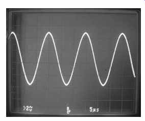
FIG. 1 Sine wave;
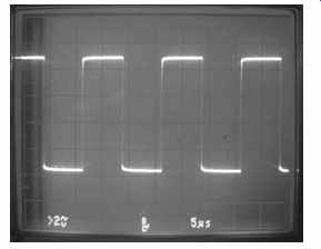
FIG. 2 Square wave;

FIG. 3 Sawtooth wave
The relative position in time of two waveforms is called their phase relationship and is expressed in degrees. As with a circle, 360 degrees represent one cycle of a waveform, regardless of how long that cycle takes. Two waveforms offset by half a cycle are 180 degrees out of phase. When there is no offset, the waveforms are in phase.
Digital signals are entirely different. Using pulses resembling square waves, digital information is always in one of two states, on or off, representing the binary numbers 1 and 0. That has tremendous advantages over the analog method, because keeping track of those two states is a lot easier than accurately moving and processing a voltage with infinitely fine gradations. Noise in a digital channel has no effect at all until it's so bad that the two states can't be found, while noise in an analog channel is very hard to separate from the desired signal and corrupts it badly. That's why scratches on an analog LP record create clicks and pops in the audio, while scratches on a CD don't. All circuits introduce some noise, so the digital method is less susceptible to degradation as it moves through various processes. Digital data is also much easier to store and manipulate, again because it has only two states to worry about.
The world of sound and light is inherently analog, though; nothing in nature exists only as ons and offs! To digitize natural phenomena like sounds and images, an ADC, or analog-to-digital converter, is used to chop the analog information into a rapid series of samples, or measurements, which are then encoded, one by one, into the binary 1's and
0's of digital data. Conversion is a complicated process that introduces quality limitations of its own, so digital is no more perfect than is analog. Digital's imperfections are different, though, and generally less objectionable.
Building Blocks
There's one heck of a variety of circuits out there! For any given function, a designer can find lots of ways to build something that works. While the circuitry "wheels" get reinvented all the time, they're all round and they all spin, so common circuit configurations are found in pretty much all products. Sometimes they have significant variations, but they're still basically the same old thing and can be recognized easily once you get familiar with them. Let's look at some common circuits you're likely to find.
The basic circuit at the heart of most stages is an amplifier of some kind.
Amplifiers have gain, which means they take steady DC from the power supply and shape it into a replica of an incoming signal, only bigger. That "bigger" can be in terms of voltage, current or both. Most voltage amplifiers also flip the signal upside down, or invert it. Sometimes that's important to the circuit's operation, but much of the time it's just an irrelevant consequence of how voltage amplifier stages are con figured.
A very common type of current amplifier is the emitter follower. This one takes its output from the emitter of a transistor, and the amplified signal mimics, or follows, the input signal, without inversion or change in voltage swing. Only the amount of current the signal can pump into a load is increased.
When amplifying analog signals, linearity, the ability to mimic the changes in the input signal faithfully without distortion, is a critical design parameter. The term comes from the graph that results if you plot the input signal against the amplified output. In a truly linear circuit, you get a straight line. The more gain, the more the line points upward, but it's still straight, indicating a ratio of input to output that doesn't change as the signal's voltage wiggles up and down. If the amplifier is driven past the point that its output reaches the power supply voltages, the transistors will be all the way on or all the way off during signal extremes, resulting in an output that no longer accurately follows the input. That's serious nonlinearity, also known as clipping because it clips off the tops and bottoms of the waveform; the amplifier simply can't go any farther. If you've ever turned up a stereo loud enough to hear ugly distortion, you've experienced clipping. Even a small amplifier driven to clipping can burn out the tweeters in a pair of speakers that normally could take the full power of a bigger amplifier without harm. The high-frequency content of a clipped waveform is much greater than that of a linearly amplified signal, thanks to the steep edges of the clipped area, so it drives disproportionate power into the tweeters. I've seen it happen. It can injure your ears, too.
Most high-fidelity audio amplifiers, and even many small ones of the sort used in pocket radios and MP3 players, use a complementary design, referred to as Class AB. Complementary amplifiers split the audio waveform into its negative-going and positive-going halves and amplify each half separately. Then they combine the two halves at the output, rebuilding the waveform. Why do that? The technique allows for excellent efficiency because almost no power is dissipated when the waveform is near the zero voltage level. Only when the input signal gets big does the amplifier draw a lot of power, keeping power usage proportional to output.
In a non-complementary design, the amplifier has to be biased to set its output halfway between ground and the power supply voltage when no signal is applied, so that the negative and positive peaks of signals can make the output swing both higher and lower in step with them. It sits there eating half the available power at all times.
Some high-end amplifiers, called Class A, actually do it that way to avoid certain subtle distortions associated with splitting and recombining the waveform. Those amplifiers sound great but run very hot and waste a lot of power.
Tuned amplifiers use resonant circuits to select a particular frequency or range of frequencies to amplify, rejecting others. They're used in radio and TV receivers to separate and boost incoming signals. See resonance in the Glossary. The very first amplifiers in a receiver that strengthen the weak signals from the antenna are called the front end. Some are tuned, and some aren't, depending on the design. Later amplifier stages, operating at a fixed frequency to which all incoming signals are converted, are called intermediate frequency, or IF, amplifiers. Those are always tuned, and they provide most of a receiver's selectivity, or ability to separate stations.
Even digital gates in integrated circuits are amplifiers. They take in digital pulses and amplify them enough to ensure that they swing all the way to the supply voltage and ground, making up for any losses that may have occurred and preventing them from accumulating until the pulses can no longer be reliably processed. These amplifiers are deliberately nonlinear; the only desired states are fully saturated, or all the way on, and fully cut off. Their linear region, where small changes in the input signal would be faithfully amplified, is made as narrow as possible. Such small wiggles in digital signals only represent noise anyway.
Oscillators generate their own signals. They have many uses, including providing timing pulses to, or clocking, microprocessors, generating tones, mixing with radio signals to convert their frequencies, and lots more. An oscillator is basically an amplifier with its output fed back to its input in phase, reinforcing the input and sending the signal around and around again indefinitely.
Oscillators can be designed to produce any of the basic waveforms. In analog signal processing circuits, sine wave oscillators are often the most useful, thanks to their purity.
Sawtooth wave oscillators are used to drive electron beams across CRTs and any time something needs to be swept and then quickly returned to its starting point. With digital circuits, which operate with pulses, square waves are the order of the day.
The significant challenge with most oscillators is setting the frequency and keeping it constant. When only a single frequency is needed, a quartz crystal or ceramic resonator can keep the oscillator very accurate. These parts resonate mechanically at the molecular level, and they're dimensionally stable, so they drift very little with temperature. The tradeoff is that a given crystal can generate only one frequency.
When frequency variability is required, as in a radio tuner, simple resonant circuits like inductor/capacitor combinations work but are not terribly stable, especially regarding thermal drift.
While early radios could tolerate some drift, today's high-precision systems simply can't. Do you really want to get up to fine-tune your digital HDTV every 20 minutes as the receiver drifts off-frequency and the picture drops out? Of course not! The receiver has to sit on its tuned frequency the moment you turn it on and stay there all day long.
The digital frequency synthesizer solves the stability problem by providing frequency agility while still being referenced to the unvarying frequency of a quartz crystal.
Pulling that off isn't simple. There are two basic techniques. In a classic hybrid analog/ digital synthesizer, an analog oscillator's frequency is controlled by a voltage from the synthesizer. The resulting frequency is digitally divided or multiplied until it matches that of the crystal. The two are then compared, and the controlling voltage is adjusted to keep them at the same frequency. So, even though the analog oscillator really isn't at the same frequency as the crystal, the comparison circuit thinks it is. This kind of circuit is called a phase-locked loop, or PLL.
Tuning the oscillator is accomplished by changing the ratio of division and multiplication, forcing the control voltage to change the true frequency to match the result of the division to that of the unvarying crystal. Many receivers have been built this way, but the method has a serious downside. In order for the comparison and correction process to work, there has to be a little error to correct. The oscillator's frequency wobbles ever so slightly as it drifts and gets corrected, resulting in a phenomenon called phase noise. The noise can be kept low, and some very nice radios worked just fine with this style of synthesizer, but it caused enough signal distortion that better methods were sought.
As digital technology advanced, chips got fast enough that the oscillator could be done away with altogether, and the required output signal could be built directly from digital data and converted to analog, in much the same way a CD player rebuilds the audio waveform of a music disc from samples. In many applications, this direct digital synthesis, or DDS, technique has replaced hybrid analog/digital synthesizer designs. Not everywhere, though: you'll still find PLL synthesizers in lots of UHF and VHF receivers because today's chips are only now getting fast enough to create the required signals at such high frequencies. The tipoff is if you see a component on the schematic that looks like a combination of a capacitor and a diode. That's a varactor, or voltage-variable capacitor, and it's what tunes the analog oscillator with the digital part of the circuit's control voltage. Where there's a varactor, there's a PLL.
PLLs are used for other purposes too. Digital data is recovered from media such as hard drives and optical discs using a PLL to synchronize the data rate to the circuit detecting it. Analog VCRs and camcorders use PLLs to recover the wobbly color information from the tape and stabilize it to the very high precision required for proper display.
Servos are a lot like PLLs, except that they slave a motor's rotational speed and phase (position at a given moment) to a reference signal. A servo regulates a DVD player's disc rotation, keeping it at whatever speed is required for a given data rate.
The rapid lens motions required to focus the laser beam on the microscopic pits and track them as they whiz by are also controlled by servos. In a VCR, servos adjust capstan motor and head drum rotation, locking them to a signal recorded on the tape, so the rotating heads will correctly trace over the recorded tracks.
Voltage regulators keep power supply voltages constant as current demand varies with circuit function. Linear regulators use a series pass transistor as a variable resistor, automatically changing the resistance to set the voltage, and dissipating the unwanted extra power as heat. They're simple and effective but also inefficient. Linear regulators handling serious power get quite hot.
Switching regulators use pulses to turn a transistor on and off like a switch, and then reconstitute the pulses passed through it back into steady DC power with a filter capacitor. Changing the pulse width permits more or less power to get through the transistor over a given period of time. Because the transistor is almost always completely on or completely off, except for the short moments when it switches states, little power is converted to heat, and there's no excess to waste, since only as much energy as needed is allowed through. Switching regulators are more complicated, and they have the potential to generate electrical noise, but their cool-running efficiency makes them very desirable, especially in battery-operated devices, where conserving power is critical.
Now that you've seen some basic terms, core concepts and circuit building blocks, go read the Glossary and see lots more. Seriously. Do it now, before going on to the next section. I know, "Grrr, this guy is such a nag." You'll thank me later. Really, you will. And, hey, there's some cool stuff there. You'll enjoy it, I promise.