AMAZON multi-meters discounts AMAZON oscilloscope discounts
Electric current that reverses direction periodically, usually many times per second. Electrical energy is ordinarily generated by a public or a private utility organization and provided to a customer, whether industrial or domestic, as alternating current.
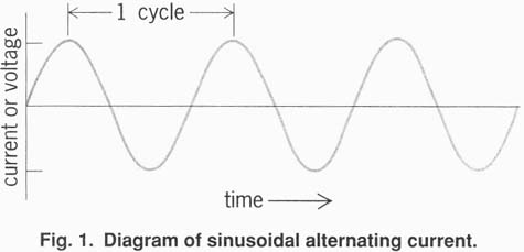
One complete period, with current flow first in one direction and then in the other, is called a cycle, and 60 cycles per second (60 hertz) is the customary frequency of alternation in the United States and in all of North America. In Europe and in many other parts of the world, 50 Hz is the standard frequency. On aircraft a higher frequency, often 400 Hz, is used to make possible lighter electrical machines.
When the term alternating current is used as an adjective, it is commonly abbreviated to ac, as in ac motor. Similarly, direct current as an adjective is abbreviated dc.
The voltage of an alternating current can be changed by a transformer. This simple, inexpensive, static device permits generation of electric power at moderate voltage, efficient transmission for many miles at high voltage, and distribution and consumption at a conveniently low voltage. With direct (unidirectional) current it is not possible to use a transformer to change voltage. On a few power lines, electric energy is transmitted for great distances as direct current, but the electric energy is generated as alternating current, transformed to a high voltage, then rectified to direct current and transmitted, then changed back to alternating current by an inverter, to be transformed down to a lower voltage for distribution and use.
In addition to permitting efficient transmission of energy, alternating current provides advantages in the design of generators and motors, and for some purposes gives better operating characteristics. Certain devices involving chokes and transformers could be operated only with difficulty, if at all, on direct current. Also, the operation of large switches (called circuit breakers) is facilitated because the instantaneous value of alternating current automatically becomes zero twice in each cycle and an opening circuit breaker need not interrupt the current but only prevent current from starting again after its instant of zero value.

Fig. 1. Diagram of sinusoidal alternating current.
Alternating current is shown diagrammatically in Fig. 1. In this diagram it is assumed that the current is alternating sinusoidally; that is, the current i is described by the equation below, where
i = Im sin 2π f t
Im is the maximum instantaneous current, f is the frequency in cycles per second (hertz), and t is the time in seconds.
A sinusoidal form of current, or voltage, is usually approximated on practical power systems because the sinusoidal form results in less expensive construction and greater efficiency of operation of electric generators, transformers, motors, and other machines.
A useful measure of alternating current is found in the ability of the current to do work, and the amount of current is correspondingly defined as the square root of the average of the square of instantaneous current, the average being taken over an integer number of cycles. This value is known as the root-mean-square (rms) or effective current. It is measured in amperes. It is a useful measure for current of any frequency. The rms value of direct current is identical with its dc value. The rms value of sinusoidally alternating current is Im/√2 (see Fig. 1 and the equation). Other useful quantities are the phase difference rp between voltage and current and the power factor.
The phase angle and power factor of voltage and current in a circuit that supplies a load are determined by the load. Thus a load of pure resistance, such as an electric heater, has unity power factor. An inductive load, such as an induction motor, has a power factor less than 1 and the current lags behind the applied voltage. A capacitive load, such as a bank of capacitors, also has a power factor less than 1, but the current leads the voltage, and the phase angle φ is a negative angle.

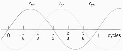
Fig. 2. Voltages of a balanced three-phase system.
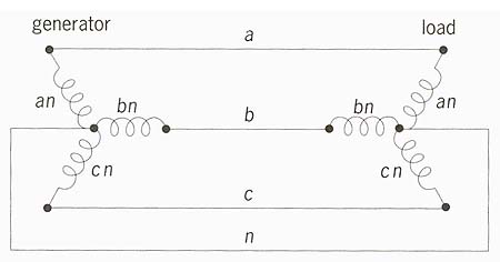
Three-phase systems are commonly used for generation, transmission, and distribution of electric power. A customer may be supplied with three-phase power, particularly if a large amount of power is used or the use of three-phase loads is desired. Small domestic customers are usually supplied with single-phase power. A three-phase system is essentially the same as three ordinary single-phase systems, with the three voltages of the three single-phase systems out of phase with each other by one-third of a cycle (120 degrees), as shown in Fig. 2. The three- phase system is balanced if the maximum voltage in each of the three phases is equal, and if the three phase angles are equal, 1/3 cycle each as shown. It is only necessary to have three wires for a three-phase system (a, b, and c of Fig. 3) plus a fourth wire n to serve as a common return or neutral conductor. On some systems the earth is used as the common or neutral conductor.

Fig. 3: Connections of a simple three-phase system.
Each phase of a three-phase system carries current and conveys power and energy. If the three loads on the three phases of the three-phase system are equal and the voltages are balanced, then the currents are balanced also. The sum of the three currents is then zero at every instant. This means that current in the common conductor (n of Fig. 3) is always zero, and that the conductor could theoretically be omitted entirely. In practice, the three currents are not usually exactly balanced, and either of two situations obtains. Either the common neutral wire n is used, in which case it carries little current (and may be of high resistance compared to the other three line wires), or else the common neutral wire n is not used, only three line wires being installed, and the three phase currents are thereby forced to add to zero even though this requirement results in some imbalance of phase voltages at the load.
The total instantaneous power from generator to load is constant (does not vary with time) in a balanced, sinusoidal, three- phase system. This results in smoother operation and less vibration of motors and other ac devices. In addition, three-phase motors and generators are more economical than single-phase machines.
AC circuits are also used to convey information. An information circuit, such as telephone, radio, or control, employs varying voltage, current, waveform, frequency, and phase. Efficiency is often low, the chief requirement being to convey accurate information even though little of the transmitted power reaches the receiving end. For further consideration of the transmission of information Google info on RADIO; TELEPHONE; WAVEFORM.
An ideal power circuit should provide the customer with electric energy always available at unchanging voltage of constant waveform and frequency, the amount of current being deter mined by the customer’s load. High efficiency is greatly desired.