AMAZON multi-meters discounts AMAZON oscilloscope discounts
The basic principle of operation of an inductive motor is based on the fact that the rotor receives its current by induction rather than with brushes and slip rings or brushes and commutators. Current can be induced into the rotor by being in close Proximity to the stator. This action is similar to the action of the primary and secondary coils of a transformer. Recall that transformers and generators that when a coil of wire is allowed to pass across magnetic flux lines, a current will be generated in the coil. This current will be 180° out of phase with the current that produced it.
When the induced current begins to flow in the squirrel-cage conductors embedded in the laminated segments of the squirrel-cage rotor, a magnetic field will be built in the rotor. The magnetic field produced by the induced current will be similar to the magnetic field produced by current that is provided to the rotor with brushes.
Since the current is induced into the rotor, no brushes are required. The strength of the field in the rotor is not as strong as a field that could be produced by passing current through brushes to a coil of wire on the rotor. That is, the magnetic field in the stator must be much stronger to compensate for the weaker field in the rotor to produce sufficient horsepower and torque.
When three-phase voltage is applied to the stator windings, a magnetic field is formed. The natural characteristic of three-phase voltage will cause the magnetic field to move from coil to coil in the stator, which appears as though the field is rotating. Fig. 1 shows an experiment to prove that the magnetic field in the stator will actually rotate. Note that the end plates and rotor have been removed from the stator. The three stator windings are connected to three-phase voltage through a switch. A large ball bearing approximately 1 inch in diameter is placed in the stator, and the switch is closed to energize the stator winding. When the magnetic field begins to form in the stator, it will begin to pull on the ball bearing. You may need to give the ball bearing a slight push with a plastic rod to get it to begin to rotate. Don't use a metal object such as a screwdriver to get the ball bearing to move because the tip of the screwdriver will be attracted to the stator by its magnetic field.
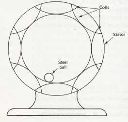
Above: Fig. 1: Experiment that shows a ball bearing placed in the stator
of a three-phase AC motor. When three-phase voltage is applied to the
rotor, a rotating magntic field will be established, and the ball bearing
will chase the rotating field around the stator. When the rotor is placed
in the stator, it will rotate in step with the rotating magnetic field.
Once the ball bearing starts to rotate, it will continue to rotate at the speed of the rotating magnetic field in the stator until the switch is opened and the stator's magnetic field has collapsed. If one reverses two of the three-phase supply voltage wires, the magnetic field will begin to rotate in the opposite direction, and when one gives the ball bearing a push to start it, it will also rotate in the opposite direction.