AMAZON multi-meters discounts AMAZON oscilloscope discounts
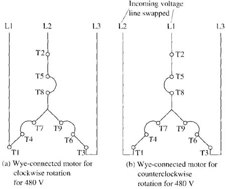
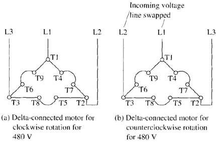
The rotation of a wye- or delta-connected motor can be changed by exchanging any two of the three phases of the incoming voltage. Fig. 1 shows diagrams for a wye-connected motor and Fig. 2 shows the diagrams for a delta-connected motor for clockwise (forward) and counterclockwise (reverse) rotation. From these diagrams notice that T1 and T2 supply voltage terminals have been exchanged in the diagram for motor reversal. In industrial applications, terminals Ti and T2 are generally switched by the contacts of the reversing motor starter. These diagrams will be useful for installation connections and troubleshooting.

Above: Fig. 1 Diagram of the wye-connected motor for clockwise and counterclockwise operation. (a) Wye-connected motor for clockwise rotation
for480 V; (b) Wye-connected motor for counterclockwise rotation for 480
V.

Above: Fig. 2 Diagram of a delta-connected motor for clockwise and counterclockwise operation. (a) Delta-connected motor for clockwise rotation
for 480 V (b) Delta-connected motor for counterclockwise rotation for
480 V.
This wiring configuration is also used when the motor is connected for plugging use. When the motor is used for plugging, it's reversed while running at full rpm. When the motor’s stator is quickly reconnected for reverse rotation by switching two of the three input voltage lines, it will quickly build up a reverse magnetic field that will begin to rotate in the opposite direction. The rotor will follow this quick change in rotation and begin to rotate in the opposite direction. This will cause the load to decrease its rpm from full in the clockwise direction to zero, and begin to rotate counterclockwise. The moment the rotor begins to rotate in the opposite direction, the power is de-energized and the rotor shaft is stopped from rapid reverse torque.