AMAZON multi-meters discounts AMAZON oscilloscope discounts
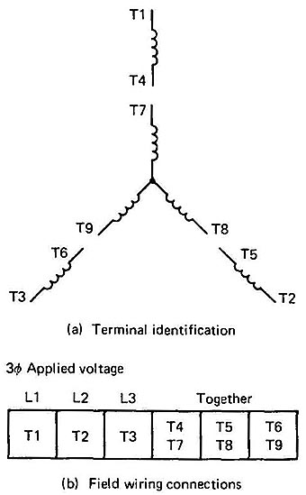
The squirrel-cage induction motor may have 6, 9, or 12 terminal leads from the ends of its coils brought out of the motor frame for field wiring connections. Field wiring connections are the connections that a technician will change right on the factory floor with the motor mounted in place. Fig. 1 shows the diagram of a nine-lead motor. Notice that the coils are positioned in the shape of the letter Y. This motor is called a wye-connected motor or star-connected motor.

Above: Fig. 1: Nine-lead, wye-connected motor.
The wye motor terminals are numbered in the clockwise direction. The two ends of the first coil are numbered Ti and T4, the second coil is numbered T2 and T5, and the third coil is numbered T3 and T6. The outside coils are isolated from each other while the inside coils are connected together at the wye point. The second diagram shows the motor connected to three-phase line voltage at Ti, T2, and T3. A table is also provided to show which terminals are connected together and which ones are connected to line voltage for the motor to operate correctly. The information provided in this table is similar to data provided on the data plate of the motor.
A technician will need to make these connections in the field when he or she is installing the motor. Wire nuts or lugs should be used to make the connections for the coil terminals and supply voltage wires. The diagram is shown for the motor so it can be connected for high voltage. The diagram indicates the high voltage is 480 volts AC. Be aware that in your area of the country the exact amount of high voltage may vary from 440 volts AC through 480 volts AC. The diagrams will be marked so that 480 volts AC represents any high voltage (440, 460, or 480 volts AC), 240 volts AC represents any low voltage (220, 230, or 240 volts AC) for a delta system, and 208 volts AC represents the low-voltage wye system.