Polyphase generators produce simultaneous multiple sinusoidal voltages that are separated by certain constant phase angles. This polyphase generation is accomplished by multiple loops rotating through the magnetic field. Similarly, polyphase motors operate with multiple-phase sinusoidal inputs.
A Basic Two-Phase Generator
Figure (a) below shows a second separate conductor loop added to a basic
single-phase generator with the two loops separated by 90°. Both loops
are mounted
on the same rotor and therefore rotate at the same speed. Loop A is
90° ahead of loop B in the direction of rotation. As they rotate, two
induced sinusoidal voltages are produced that are 90° apart in phase, as shown Figure (b).

A Basic Three-Phase Generator
Figure (a) shows a polyphase generator with three separate conductor loops placed at 120° intervals around the rotor. This configuration generates three sinusoidal voltages that are separated from each other by phase angles of 120°, as shown in Figure (b).

A Basic Three-Phase Induction Motor
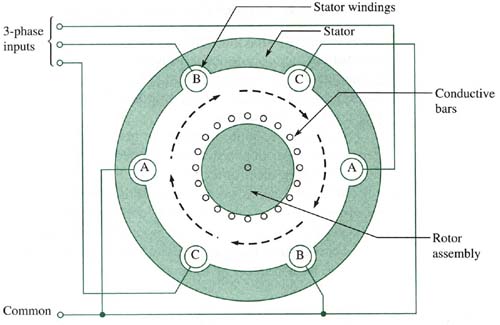
The most common type of ac motor is the three-phase induction motor. Basically, it consists of a stator with stator windings and a rotor assembly constructed as a cylindrical frame of metal bars arranged in a squirrel-cage type configuration. A basic end-view diagram is shown in the figure below.
When the three-phase voltages are applied to the stator windings, a rotating
magnetic field is established. As the magnetic field rotates, currents
are induced in the conductors of the squirrel-cage rotor. The interaction
of the induced currents and the magnetic field produces forces that cause
the rotor to also rotate.
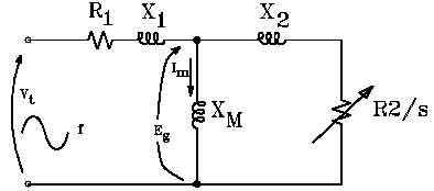
Here is the equivalent circuit for an AC induction motor:

In applications where the turning speed of a three-phase motor needs to be changed, a variable-frequency drive (VFD) is often used.
