Articles
Forum
Glossary
Books
Sitemap
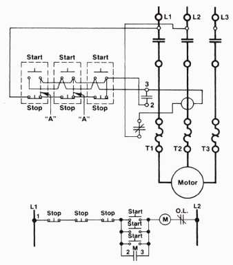 Additional start and stop push buttons may
be needed on a system that is very large. For example, if the system
is installed over a large area, such as for a long conveyor system that
may be over several hundred feet long, it would be inconvenient and unsafe
to have one start and stop button at only one end of the system. To make
the system more safe and to make it more convenient to start and stop
the system, push-button switches can be installed every 40 feet. Each
additional start button should be connected in parallel with the first
start button, and all additional stop buttons should be connected in
series with the original stop button. Figure 1 shows examples of
the additional start and stop push buttons in a three- wire circuit.
Additional start and stop push buttons may
be needed on a system that is very large. For example, if the system
is installed over a large area, such as for a long conveyor system that
may be over several hundred feet long, it would be inconvenient and unsafe
to have one start and stop button at only one end of the system. To make
the system more safe and to make it more convenient to start and stop
the system, push-button switches can be installed every 40 feet. Each
additional start button should be connected in parallel with the first
start button, and all additional stop buttons should be connected in
series with the original stop button. Figure 1 shows examples of
the additional start and stop push buttons in a three- wire circuit.
Right: Fig. 1: The wiring diagram for a three-wire control circuit with additional start and stop push buttons added to the circuit is shown at the top of this figure, and the ladder diagram of just the control circuit is shown at the bottom.


