Connecting rods
No part is more critical than the connecting rod and none more conservatively designed ( FIG. 50).
Construction
All diesel engines employ two-piece, H-section rods, heavily faired at the transitions between bearing sections, and forged from medium-carbon steel or from that ubiquitous alloy, SAE 4140. The small end is generally closed and fitted with a replaceable bushing (some automotive OEMs don’t catalog replacement bushings, but a component machinist can work around that). The big end carries a two-piece precision insert bearing. A few rods terminate in a slipper, which bolts to the piston pin, as shown in FIG. 51. Open construction makes the whole length of the pin available as a bearing surface.
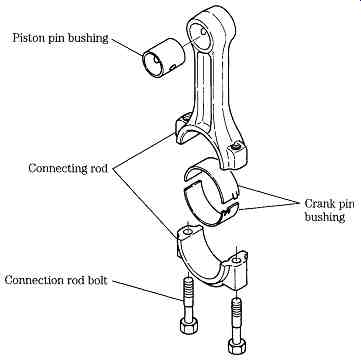 FIG. 50 Typical connecting rod and bearing assembly. A rifle-drilled oil
passage indexes with ports in both the small-end bushing and upper big-end
insert. Yanmar Diesel Engine Co. Ltd.
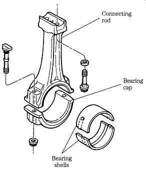
FIG. 51 Detroit Diesel slipper-type connecting rod, used with the articulated
piston shown in FIG. 44.
Whenever possible, interface between the shank and cap should be perpendicular to the crankshaft centerline. This configuration reduces side forces on the cap.
However, the rod must be split at an angle to allow disassembly through the bore when crankpin diameter is large (as in Onan engines) or to prevent contact with other parts (Deere 6076).
Connecting rods have a definite orientation relative to the piston and to the cap.
The former is a function of transverse oil ports, drilled in the rod shank; the latter reflects the way connecting rods are manufactured. The relatively small connecting rods that we are dealing with are forged in one piece. Then the cap is separated (sometimes merely by snapping it off), assembled, and honed to size. Reversing the cap or installing a cap from another rod destroys bearing circularity. Typically, a mismatched assembly overheats and seizes within a few crankshaft revolutions. Rod shanks and caps carry match marks, and both parts are identified by cylinder number (Figs. 52 and 53). Errors can be eliminated by double- and triple-checking match mark alignment and cylinder numbers. Mechanics do well to observe the rule that no more than one rod cap should be disassembled at a time.
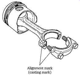
FIG. 52 Most rods and caps carry cast match marks as shown on this Yanmar
assembly. Cylinder numbers will be stamped on the other side of the rod.
Service
The number stamped on the rod shank and cap should correspond to the cylinder number. Sometimes these numbers are scrambled or missing, and the mechanic must supply them. Stamp the correct numbers on the pads provided and, to prevent con fusion, deface the originals.
Mike rod journals at several places across the diameter, repeating the measurements on both sides to detect taper (FIG. 54). Inertial forces tend to stretch the rod cap and pinch the ends together. When this condition is present, the machinist should mill a few thousandths off the cap interface and, with the cap assembled and torqued, machine the journal to size. Typically, this is done with a reamer, although automatic honing machines, such as the Sunnen or the Danish-made AMC, produce a finer, more consistent surface.
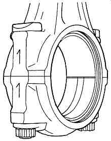
FIG. 53 Rod assembly for No. 1 cylinder on a Detroit Diesel engine.
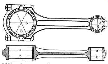
FIG. 54 Journal measurement points. Marine Engine Div., Chrysler Corp.
The machinist should check the alignment of each connecting rod with a fixture similar to the one shown in FIG. 55. Even so, these matters should not be entirely left to the discretion of the machinist. It’s always prudent to check the work against the testimony of the engine. Rod and crankpin misalignment produces telltale wear patterns on piston thrust faces, on pin bores, and on the retainers and retainer grooves.
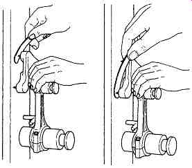
FIG. 55 Rod alignment fixture used to detect bending and torsional misalignment. Yanmar Diesel Engine Co. Ltd.
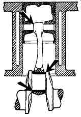
FIG. 56 A bent rod concentrates bearing wear at the points shown. Ford Motor Co.
A bent rod tilts the piston, localizing bearing wear at the points shown in FIG. 56, This condition might also be reflected by an hourglass-shaped wear pattern on the thrust faces, as illustrated in FIG. 57. A twisted rod imparts a rocking motion to the piston, concentrating wear on the ring band and skirt edges ( FIG. 58). Crankshaft taper generates thrust, which might scuff the skirt and could drive the pin through one or the other retainer.
Bent or twisted rods generally can be straightened, although some manufacturers warn against the practice.
Most rod bolts can be reused, if visual and magnetic-particle testing fails to reveal any flaws. Some recently developed torque-to-yield bolts can also be reused; earlier types were sacrificial. Rod-bolt nuts should be replaced, regardless of the fastener type.
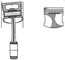
FIG. 57 Another effect of loss of rod parallelism is to tilt the piston and, in extreme cases, produce the wear pattern shown on the left. Sealed Power
Corp.
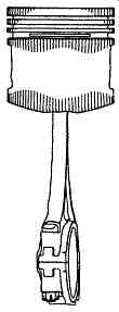
FIG. 58 A twisted connecting rod causes the piston to rock, a condition that can be signaled by an elliptical wear pattern. Sealed Power Corp.

FIG. 59 Interpreting Magnaflux indications. Detroit Diesel
Used rods should be Magna-fluxed. Interpretation of the crack structure thus revealed requires some judgment. Any rod that has seen service will develop cracks. One must distinguish between inconsequential surface flaws and cracks that can lead to structural failure. The drawing in FIG. 59 can serve as a guide.
In general, longitudinal cracks are not serious enough unless they are / in. deep, which can be determined by grinding at the center of the crack. Transverse cracks are causes of concern because they can be the first indication of fatigue. If the cracks don’t extend over the edges of the H-section, are no more than 1/2 in. long, and less than 1/64 in. deep, they can be ground and feathered. Cracks over the H-section can be removed if 0.005 in. deep or less. Cracks in the small end are cause for rejection.
Small-end bushings are pressed into place with reference to the oil port and are finish-reamed. Loose bushings are a sign that the rod has overheated, and they can cause a major failure by turning and blocking the oil port.
What has been described are standard, industry-wide practices. One can go much further in the quest for a more perfect, less problematic engine. For example, it’s good practice to match the weight of piston and rod assemblies to within 10 g or so-even when parts are not to be sent out for balancing. Surplus weight can be ground from the inner edges of the piston skirts. Some mechanics assemble one piston and rod to several crankpins. Differences in deck height between No. 1 and the last cylinder of the bank indicate an alignment problem, either between crankshaft throws or between the crankshaft centerline and deck.
Crankshafts
At this point we have progressed to the heart of the engine, the place where its durability will be finally established.
Construction
Crankshafts for the class of engine under discussion are, for the most part, steel forgings. Materials range from ordinary carbon steels to expensive alloys such as chrome-moly SAE 4140. A number of automotive engines and lightly stressed stationary power plants get by with cast-iron shafts, usually recognized by sharp, well-defined parting lines on the webs and by cored crankpins. Forging blurs the parting lines and mandates solid crankpins, which, however, are drilled for lubrication.
Most crank journals are induction-hardened, a process that leaves a soft, fatigue resistant core under a hardened "skin." Hardness averages about 55 on the Rockwell scale and extends to a depth of between 0.020-0.060 in. in order to accommodate regrinding. But a cautious machinist will test crankshaft hardness after removing any amount of metal.
A few extreme-duty crankshafts are hardened by a proprietary process known as Tufftriding. Wearing quality is comparable to that provided by chrome plating, but unlike chromium, the process does not adversely affect the fatigue life of the shaft.
Service
Remove the crankshaft from the block-a hoist will be required for the heavier shafts-and make this series of preliminary inspections:
• If a main bearing cap or rod has turned blue, discard the shaft, together with the associated cap or rod. The metallurgical changes that have occurred are irreversible. By the same token, be very leery of a crankshaft that is known to have suffered a harmonic balancer failure.
• Check the fit of a new key in the accessory-drive keyway. There should be no perceptible wobble. A competent machinist can rework worn keyways and, if necessary, save the shaft by fabricating an oversized key.
• Check the timing-gear teeth for wear and chipping. Magnetic-particle testing can be of some value when applied to the hub area, but cannot detect the subsurface cracks that signal incipient gear-tooth failure. Timing gear sprockets and related hardware should be replaced as a routine precaution during major repairs.
• Mike the journals and pins as shown in FIG. 60. Compare taper, out-of roundness, and diameter against factory wear limits.
• If corrective machining does not appear necessary, remove with crocus cloth all light scratches and the superficial ridging left by bearing oil grooves. Tear off a strip of crocus cloth long enough to encircle the journal.
Wrap the cloth with a leather thong, crossing the ends, to apply force evenly over the whole diameter of the journal. Work the crocus cloth vigorously, stopping at intervals to check progress. An Armstrong grinder works surprisingly fast.
• Using an EZ-Out or hex wrench, remove the plugs capping the oil pas sages. Back-drilled sections of these passages serve as chip catchers, and must be thoroughly cleaned. Compressed air, shown in FIG. 61, helps but is no substitute for rifle-bore brushes, solvent, and elbow grease. Clean the plugs, seal with Loctite, and assemble.
• Check trueness with one or, preferably, tandem dial indicators while rotating the crank in precision V-blocks ( FIG. 62).

FIG. 60 Crankshaft measurement points. Marine Engine Div., Chrysler Corp.
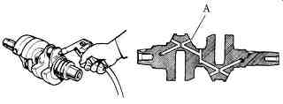
FIG. 61 Blind runs in the crankshaft oiling circuit must be opened, mechanically
cleaned, and resealed. Lombardini
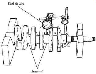
FIG. 62 Checking crankshaft straightness using the center bearing as the referent. Yanmar Diesel Engine Co. Ltd.
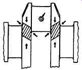
FIG. 63 Most crankshaft loads pass through the webs. Detroit Diesel
Flaw testing
Flaw testing is generally done with the Magnaflux process, although some shops prefer to use the fluorescent-particle method. Both function on the principle that cracks in the surface of the crankshaft take on magnetic polarity when the crank is put in a magnetic field. Iron particles adhere to the edges of these cracks, making them visible. The fluorescent particle method is particularly sensitive because the metal particles fluoresce and glow under black light.
Most cracks are of little concern because the shaft is loaded only at the points indicated in FIG. 63. The strength of the shaft is impaired by crack formations which follow these stresses, as shown in FIG. 64. These cracks radiate out at 45° to the crank centerline and will eventually result in a complete break.
Abnormal bending forces are generated by main-bearing bore misalignment, improperly fitted bearings, loose main-bearing caps, unbalanced pulleys, or over tightened belts. Cracks caused by bending start at the crankpin fillet and progress diagonally across.
The distribution of cracks caused by torsional (or twisting) forces is the same as for bending forces. All crankshafts have a natural period of torsional vibration, which is influenced by the length/diameter ratio of the crank, the overlap between crankpins and main journals, and the kind of material used. Engineers are careful to design the crankshaft so that its natural periodicity occurs at a much higher speed than the engine is capable of turning. However, a loose flywheel or vibration damper can cause the crank to wind and unwind like a giant spring. Unusual loads, especially when felt in conjunction with a maladjusted governor, can also cause torsional damage.
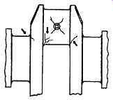
FIG. 64 Typical fatigue crack pat terns, all of them Critical. Detroit Diesel.

FIG. 65 Fillet profiles. Sharp edges, flat surfaces, and overly wide profiles should be avoided.
Rolled, as opposed to ground, fillets extend fatigue life by as much as 60%, but few shops have the necessary equipment. Detroit Diesel
Crankshaft grinding
Bearings are available in small oversizes (0.001 and 0.002 in.) to compensate for wear. The first regrind is 0.010 in. Some crankshafts will tolerate as much as 0.040 in., although the heat treatment is endangered at this depth. The crankpin and main journal fillets deserve special attention. Flat fillets invite trouble, because they act as stress risers. Gently radius the fillets as shown in the left drawing in FIG. 65.
All journals and pins should be ground, even if only one has failed. Use plenty of lubricant to reduce the possibility of burning the journal. Radius the oil holes with a stone and check the crankshaft again for flaws with one of the magnetic particle methods.
Surface hardness should be checked after machining and before the crank receives final polishing. Perhaps the quickest and surest way to do this is to use Tarasov etch.
Clean the shaft with scouring powder or a good commercial solvent. Wash thoroughly and rinse with alcohol. Apply etching solution No. 1 (a solution of 4 parts nitric acid in 96 parts water). It’s important to pour the acid into the water, not vice versa.
Rinse with clean water and dry. If you use compressed air, see that the system filter traps are clean. Apply solution No. 2, which consists of 2 parts hydrochloric acid in 98 parts acetone. Acetone is highly flammable and has a sharp odor that can produce dizziness or other unpleasant reactions when used in unventilated areas, so allow yourself plenty of breathing room.
The shaft will go through a color change if it has been burned. Areas that have been hardened by excessive heat will appear white; annealed areas turn black or dark gray. Unaffected areas are neutral gray. If any color other than gray is present, the shaft should be scrapped and the machinist should try again, this time with a softer wheel, a slower feed rate, or a higher work spindle speed. Some experimentation might be necessary to find a combination that works.
Cranks that have been Tufftrided must be treated after grinding to restore full hardness. One test is chemical: a 10% solution of copper ammonium chloride and water applied to the crankshaft reacts almost immediately by turning brown if a traditional heat treatment has been applied. There will be no reaction in 10 seconds if the crankshaft is Tufftrided. Another test is mechanical: Tufftriding is applied to the whole crankshaft, not just to the bearing journals. If a file skates ineffectually over the webs without cutting, one can assume that the shaft is Tufftrided.
Any heavy-duty crankshaft, forged or cast, can benefit from Tufftriding, if the appropriate bearing material is specified. This treatment is especially beneficial when the manufacturer has neglected to treat journal fillets. The abrupt change in hardness acts as a stress riser. Treatment should be preceded by heating the crankshaft for several hours at a temperature above 1060°F. It might be necessary to re-straighten the crankshaft.
Camshafts and related parts
Inspect the accessory drive gear train for tooth damage and lash. Crank and camshaft gears are pressed on their shafts and further secured by pins, keys, or bolts.
OHV cam and balance shafts are supported on bushings, which require a special tool, shown in FIG. 66, to extract and install. Normally, the machinist services in-block bushings, removing the old bushings and installing replacements that, depending upon engine type, might require finishing. The OEM practice of leaving bushing bores unfinished and reaming installed bushings to size complicates the rebuilding process. It’s also possible for bushings to spin in their bosses, a condition that can be corrected by sleeving.
Camshaft lobes are the most heavily loaded parts of the engine, with unit pressures in excess of 50,000 psi at idle. Valve lifters, whether hydraulic or mechanical, are normally offset relatively to the lobes, so that contact occurs over about half of the cam surface. This offset, together with a barely visible convexity ground on the lifter foot tends to turn the lifter as it reciprocates. As the parts wear, the contact area increases and eventually spreads over the whole width of the lobe. Thus, if you find a camshaft with one or more "widetrack" lobes, scrap the cam, together with the complete lifter set. Although the condition is rare in diesel engines, overspeeding and consequent valve float might batter the flat toes of the lobes into points. FIG. 67, which illustrates lobe wear measurements, inadvertently illustrates this condition.
The same two-point measurements should be made on the journals.
Normally, hydraulic valve lifters are replaced during a rebuild; attempting to clean used lifters is a monumental waste of time. This means that the camshaft must also be replaced, because new lifters won’t live with a used camshaft (and vice versa). Assemble with the special cam lubricant provided, smearing the grease over each lobe and lifter foot. Oil can be used on the journals.
Replacement hydraulic lifters normally are charged with oil as received, and ample time must be allowed for bleed when screwing down the rocker arms on OHV engines. Some valves will be open; if the rockers are tightened too quickly, pushrods will bend. As mentioned earlier, the low bleed-down rates of Oldsmobile 350 lifters make rocker assembly an exercise in patience; most other rockers can be assembled in a few minutes of careful wrenching.

FIG. 66 Camshaft bearing tool. Marine Engine Div., Chrysler Corp.
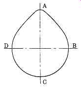
FIG. 67 Cam lobe measurement points. Navista.
Break in the camshaft exactly per maker's instructions. Otherwise, it will score.
Prev. | Next
Home top
of page Similar articles