Roughly 30% of the heat energy produced by combustion must be dissipated by the cooling system. In addition, the cooling system can be required to absorb heat from aftercoolers, engine and transmission oil coolers, hydraulic oil coolers, and other sources.
Air cooling
The great advantage of air cooling is its simplicity. There are no radiators, pumps, or hoses to add dead weight and eventually fail. On the other hand, the cooling fins and aluminum castings that promote heat transfer also transmit sound.
Air-cooled engines are noisy. Nor does air cooling provide the precise temperature control necessary for good efficiency and low exhaust emissions. The centrifugal fan behaves like a turbocharger, pumping out too much air at high speeds and too little when the engine bogs under load.
Most air-cooled engines are small single- and twin-cylinder units developing less than 40 hp. But the concept is also applied to larger engines. Deutz builds a range of modular air-cooled engines of up to 500 hp, some of which are even used in marine applications. Most of the world's armored vehicles are powered by air-cooled diesels.
FIG. 1 shows the cooling arrangement for small utility engines. The flywheel mounted fan generates air flow that is directed over the cylinder by means of shrouding. Few of these engines are equipped with temperature gauges, which is a serious oversight. The operator can measure oil temperature with a thermometer placed in the dipstick boss to a depth of about 5/16 in. below the end of the stick, but well clear of metal surfaces. Maximum permissible oil temperature is a judgment call, with one manufacturer suggesting that it should not exceed 210 deg. F (99 deg. C) above ambient.
The thermostatically controlled shutter used by Onan gives an idea of the normal range of air-outlet temperatures (Fig. 12). The thermostat, mounted in the air outlet, begins to open the shutter when temperature reaches 120 deg. F (49 deg. C) and extends fully at 140 deg. F (60 deg. C). A second thermostat shuts off fuel delivery when outlet-air temperature reaches 250 deg. F (121 deg. C). It is fair to say that outlet-air tempera ture should not exceed 45 deg. F above ambient under load.
Chronic overheating means that the engine is undersized for the application. Other than periodically cleaning the fins and checking the fit of the tin work, there is little a mechanic can do to improve cooling. A very light coat of dull black paint applied over bare metal on exposed surfaces makes a marginal improvement in radiation.
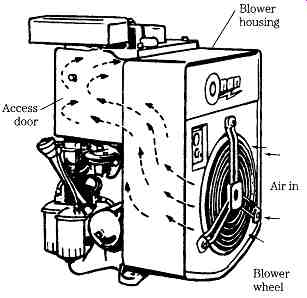
FIG. 1 Air-flow for an air-cooled engine. Courtesy Onan

FIG. 2 Thermostatically controlled shutter provides improved temperature control.
Onan

FIG. 3 Coolant flow in system without a provision for air purging. Thermostat closed
(A) and open (B). International

FIG. 4 Coolant flow in a self-purging system. Thermostat closed (A) and open
(B). International
Liquid cooling
Early engines were cooled by water in a hopper above the cylinders that was refilled as the water boiled off. Modern practice is to employ closed systems with a radiator or other form of heat exchanger, one or more circulation pumps, and a thermostat. FIG. 3 illustrates the basic system. When the engine is cold, the thermostat closes to confine most of the coolant within the water jacket. A small fraction of the coolant makes its way to the radiator through an internal bleed port in the thermostat. As shown in the drawings, the bypass often takes the form of a small-diameter hose running from below the thermostat housing to the pump. Some circulation is necessary to prevent local hot-spots in the water jacket.
As water temperature rises-a typical figure is 190 deg. F (87.8 deg. C), the thermostat opens. Flow then passes from the water jacket through the top hose to the radiator and out of the lower hose to the water pump.
Most cooling systems include one or two additional hoses that function to vent air to the radiator or expansion tank. The system depicted in Fig. 4 employs two lines that convey aerated coolant to the radiator header. Air enters from splash entrapment (as, for example, when the radiator is filled from a bucket), past the water-pump seal, and by way of compression leaks across the head gasket. Besides reducing heat transfer-air removes heat 3500 times less efficiently than water-air increases the tendency of the water pump to lose pressure through cavitation.
Modern cooling systems employ an expansion tank, connected to the radiator-cap overflow and, for stationary engines, discharging into the radiator-return line. This expansion, surge, or degassing tank vents entrapped air and exhaust gases, collects overflow, and provides convenient means of replenishing the coolant. If it is to vent gases, the tank must be located above the thermostat housing, which is normally at the highest wetted point on the engine block.
Figures 5 and 6 illustrate two fresh-water marine systems, one using a sea water-cooled heat exchanger and the other a keel cooler. Expansion tanks are clearly shown.

FIG. 5 Marine application using a seawater-cooled heat exchanger and expansion
tank. Caterpillar Inc.
As illustrated in Fig. 7, standard practice is to distribute coolant to the cylinder liners through an external manifold. Many engines have an oil cooler in series with the main cooling circuit, and multiple liquid-cooled accessories, such as an aftercooler, turbocharger, torque converter, cab heater, and vehicle brakes, plumbed in parallel.
Coolant
Diesel manufacturers recommend a 50-50 mixture of low-silicate ethylene glycol and distilled water. This mixture gives -34 deg. F (-37 deg. C) protection against freezing and raises the boiling point to 226 deg. F (107 deg. C). Pressurization raises the boiling point further.
Some diesel manufacturers permit the use of standard automotive antifreezes that meet ASTM D3306 specifications. Others insist upon the more stringent D4985 or D6210 specification. D4985 has an inhibitor life of 3000 operating hours or one year, and D6210 is good for 3000 hours or three years. The additive package in Caterpillar ELC (Extended Life Coolant), which is incompatible with other antifreezes, provides protection for 12,000 hours or six years. Depending upon the type of antifreeze used, long-term protection may require that additive package be periodically replenished. Check with your dealer.
Soluble oils and methyl alcohol have no place in modern engines.
While there is no substitute for distilled or ionized water, there are times when operators are forced to use whatever is available. The water should meet these minimum specifications:

FIG. 6 Marine application with a keel cooler. Courtesy Caterpillar Inc.

FIG. 7 A radiator, oil cooler, and water jacket make up the basic coolant circuit.
Caterpillar Inc.
The local water utility or agricultural agent can provide data on water quality.
CAUTION: do not overfill radiators. Topping off the radiator or expansion tank when the engine is cold merely wastes coolant, since the surplus goes out the over flow when the engine warms. Continued overfilling dilutes the antifreeze.
A major drawback associated with ethylene glycol is the way it reacts with lube oil. Should a leak develop at the head gasket or oil cooler, shut the engine down immediately and make the necessary repairs. Assuming that the engine will still turn over, you might be able to avert a complete teardown by flushing the lubrication system with Butyl Cellosolve or an equivalent product. But check with the factory first, since the procedure was developed for Detroit two-cycles and could damage more heavily loaded engines.
The procedure consists of replacing the contaminated lube oil with a 50-50 mix of Cellosolve and SAE 10 oil. The engine is run at 1200 no-load rpm for one hour, then for another 15 minutes with pure SAE 10 in the crankcase. If the bearings survive, that is, if oil pressure remains steady and no knocks are heard, the operation was successful and the engine may be returned to service.
Overheating
Most diesel temperature gauges are calibrated to show overheating at around 226 deg. F (108 deg. C), but panel gauges cannot be trusted. Verify with an accurate thermometer, and preferably one of the remote-sensing infrared types that can be used to detect hot spots in the radiator. Other signs of possible overheating include steam from the radiator overflow after shutdown, coolant leaks, and low coolant levels.
Low coolant levels can be both a cause of overheating and its result, as coolant boils off and escapes out the vented cap or expansion tank. In any event, refill the radiator and see if the problem recurs.
Severe overheating results in blown head gaskets, warped or cracked cylinder heads, and scored pistons. The pistons for the aft cylinders usually fail first. As a point of interest, the style of combustion chamber influences how pistons seize.
Pistons for IDI engines generally bind at the area just below the upper ring land. DI pistons are more likely to seize on their thrust faces.
Table 1 lists the most common causes of overheating.
Table 1. Overheating problems and causes
Problem --- Possible causes
========
Problem:
Low coolant level Low heat transfer Insufficient coolant flow Insufficient coolant pressure; Coolant overflow
Insufficient air flow throug radiator
High inlet air temperature or restriction
Exhaust restriction
-- --- ---
Possible causes
External leaks at hoses, radiator, and radiator cap
Internal leaks at head gasket, cylinder head, aftercooler, torque-converter cooler, etc.
Clogged radiator; Scale accumulations in water jacket Marine growth on keel cooler or insufficient flow of raw water through heat exchanger; Thermostat stuck closed Loose water-pump belts; Water-pump failure; Clogged radiator core; Failed radiator pressure cap; Failed coolant-pressure relief valve (when fitted) Combustion gases entering system-loose or cracked cylinder head, leaks at head gasket, precombustion chamber, cylinder liner Entrapped air in cooling system Low or no fan speed-electric or hydraulic fan drive failure, loose belts, worn pulleys Fan installed backwards Shutter not opening Shrouding not installed properly Clogged air cleaner Clogged aftercooler Turbocharger failure
Turbocharger failure; Water in muffler or loose muffler baffle
Clogged particulate trap/catalytic converter (when fitted)
========
Coolant leaks
Loss of coolant results from intrusion of combustion gases into the water jacket, a failed radiator cap or cap seal, and leaks. Most leaks are obvious, but look for tell tale rust stains at gasketed joints with special attention to the block/head interface.
Freeze plugs rust from the inside out. Very small leaks can be found by coloring the coolant with dye and pressurizing the system with a hand pump.
Corrosion and scale
A fairly accurate idea of the corrosion present in the water jacket can be had by removing the radiator hose from the thermostat housing. A film of light rust that wipes off with rag may be present on new engines and has no significance. Layered rust is cause for concern.
Most corrosion can be blamed on poor maintenance. Ethylene glycol antifreeze is safe so long as its additive package remains active. When in doubt about the condition of the antifreeze, change it. Antifreeze test kits for nitrite and phosphate inhibitors quickly pay for themselves in fleet service.
The pH level of the coolant should be neutral, that is between 7.0 and 10.5.
Below 7.0 the coolant is acidic and dissolves iron; above 10.5 it turns alkaline and attacks aluminum, solder, and other nonferrous metals. The test apparatus is avail able from chemical supply houses.
Another, and sometimes difficult to correct, source of corrosion is electrolysis.
When two dissimilar metals are subject to voltage, the least "noble" of these metals erodes. The coolant acts as the conductor and aluminum becomes the sacrificial metal, eroding about twice as rapidly as cast iron under the same voltage. Check for loose, dirty, or rusted ground connections, missing engine-to-ground straps, and for the presence of sacrificial anodes on marine applications. Using a digital ohmmeter, check the resistance between each grounded electrical component and the battery negative post. Resistance should be less than 0.03_. A higher reading means that the component is not properly grounded.
Exhaust gas seeping into the coolant also contributes to corrosion. Make up a hose connection to a sensor boss on the thermostat housing and collect the coolant in a glass container. Run the engine at normal temperature under load.
An occasional bubble is acceptable, but a steady stream of bubbles indicates an exhaust leak.
Scale consists of calcium carbonate and sulfate, iron, copper, silica, and trace metals. According to General Motors, 1/16 in. of scale is the thermal equivalent of 4 1/ 2 in. of cast iron. The primary source of scale is hard water that does not meet the minimum specifications listed earlier.
Cleaning
Reverse flushing removes loose rust and silt from the radiator and block. To flush the radiator, disconnect both hoses and insert a flushing gun, connected to a 100-psi air line, into the lower hose (Fig. 8 A). Fill the radiator and inject air in short bursts. Continue until the water flows freely. With the thermostat removed, do the same for the block (Fig. 8 B).
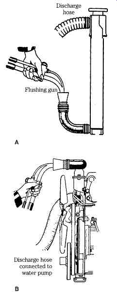
FIG. 8 Reverse flushing the radiator (A) and the block (B). GM Bedford Diesel
Two-part cleaners, consisting of oxalic acid and a neutralizing compound, can remove light rust and scale deposits without taking the engine out of service. Any of the commercial products work, or you can mix your own acid by adding 2 lb of sodium bisulfate with 10 US gal of water. The neutralizer consists of 1 / 2 lb of sodium carbonate crystals per 10 gal of water.
The presence of oil in the coolant can usually be traced to a leaking oil or transmission cooler, although other sources cannot be dismissed. A leak can develop across any interface that separates pressurized lube oil from coolant. Oil leaks result in local overheating that does not register on the temperature gauge. According to Detroit Diesel 1.25% of oil by volume in the coolant increases firedeck temperature by 15%.
Once the leak is found and repaired, drain the cooling system and refill with water and two cups of non-foaming dishwasher detergent. Run the engine for 20 minutes or so, adding more detergent as necessary to emulsify the oil. Drain the system, flush with water to remove all traces of detergent, and refill with approved coolant.
Cavitation erosion
Wet cylinder liners flex under combustion pressures and pull away from the surrounding coolant. Air bubbles form in the void, attach themselves to the cylinder liners and implode, leaving tiny pits in their wake. The action is progressive and, at some point, the pitting breaks through to admit coolant into the cylinder (Fig. 9).
New liners have protection in the form of an oxide coating. But the oxide eventually pits and one must rely on additives, such as nitrates, to inhibit bubble formation and slow the rate of metal loss. The operator should avoid lugging the engine, which increases the amplitude of vibration, and do what he can to minimize piston slap. The fewer cold starts, the better. But cavitation erosion will be with us as long as diesel engines use wet liners.

FIG. 9 Cavitation erosion results in coolant leaks into the cylinders. Caterpillar
Inc.
Overcooling
Standard practice is to size the cooling system to yield a top radiator-tank temperature of 210 deg. F (99 deg. C) at a maximum ambient temperature of 110 deg. F (43 deg. C).
A properly calibrated thermostat and the use of radiator shutters in cold climates should prevent overcooling and the resulting gum and carbon deposits.
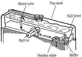
FIG. 10 Conventional down-flow radiator. The baffle distributes coolant over
the width of the core and traps gas bubbles that vent through the bleed tube.
International
Radiators
Heavy-duty radiators have large frontal areas and free-flowing cores with no more than 10 or 11 fins/in. These radiators are square, or nearly square, so that a single fan can pull or push air over most of the core surface. As shown in Fig. 10, coolant flows down from the header tank, usually made of brass, across a baffle, and through the vertical copper tubes. In the better examples, the tubes are brazed to the header tank. The Modine Beta Weld process, originally developed for off-road-vehicle radiators, produces a stronger and more reliable joint than soldering.
Radiators for industrial/commercial applications have a built-in safety factor known as the drawdown capability. Standards vary somewhat with the engine maker, but a properly sized system can lose between 10% or 15% of its coolant without overheating. FIG. 11 charts this relationship.
Passenger-car radiators come out of a different tradition. Low hood lines result in elongated radiators, which often require two fans to cool. Since the early 1990s, aluminum has been specified for the core, and header tanks are often made of plastic. Designers compensate for loss of heat transfer-aluminum con ducts heat only about half as well as copper-by narrowing the fin spacing and making the cores thicker. These almost solid radiators require large amounts of fan power to cool.
Automotive cooling systems must be accepted as they are, since the engineering that goes into them and underhood space limitations preclude much by way of modification. But cooling systems for stationary applications can often be improved with a bit of judicious tinkering. For example, most have simple box shrouds that can be replaced by much more efficient venturi shrouds. Other modifications are discussed below under "Fans." As far as routine maintenance goes, green slime (chromium hydroxide) and sediment can be removed by reverse flushing the core or with oxalic acid. When over heating persists, farm out the radiator to a specialist for chemical cleaning.
Fins, especially closely spaced fins, tend to clog and should periodically be cleaned with compressed air, high-pressure water, or steam. Some of the worst offenders are off-road vehicles that splatter their radiators with mud and fork-lift trucks that handle cotton or other fibrous products.
Leaks in brass and copper radiators can often be repaired on site. The secret lies in the soldering, or more exactly, in the preparation for soldering. Remove all traces of grease and oil from the damaged area. Then, using fine emery paper, sand down the area to bright metal. Apply generous amount of flux (a mixture of muriatic acid and zinc powder) and solder. Hard, 60/40 solder makes a stronger joint than the softer grades. If the solder bubbles and skates, the surface is still not clean. The solder should sink into the base metal and harden with a mirror-like glaze. Once the repair is made, wipe off all traces of flux.
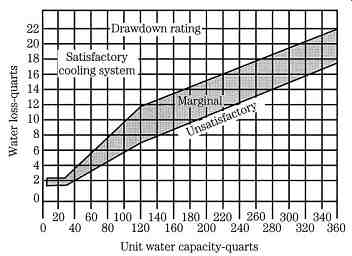
FIG. 11 The drawdown rating refers to the system's ability to function with
reduced coolant volume. Acceptable drawdown capacities are shown here for systems
with capacities of up to 360 quarts. International
Pressure caps
Pressure, generated by the radiator cap, raises the boiling point of the coolant (Fig. 12) and reduces the tendency of the water pump to cavitate. The cap includes two check valves, one that opens under vacuum (1) and a second, spring loaded valve (2) that regulates system pressure (Fig. 13). Pressures range from 3 or 3 psi to more than 15 psi for engines operating at high altitudes.
A pressure cap that fails to hold pressure can cause boiling and loss of coolant, which ultimately results in overheating. A cap that fails to vent after shutdown, when the volume of coolant shrinks, often collapses the radiator hoses.
And finally, a word of caution. Radiator caps cam open in two stages. The first stage releases pressure and diverts coolant downward, away from the mechanic's hands. The second stage frees the cap from the radiator neck. All manufacturers warn that the engine should be allowed to cool before removing the cap. Risk increases with temperature and altitude. Releasing pressure on an overheated engine releases a geyser of boiling coolant and superheated steam that, while directed downward, rebounds off adjacent surfaces.

FIG. 12 Graph showing how the boiling point of water varies with altitude and
pressure. Caterpillar Inc.
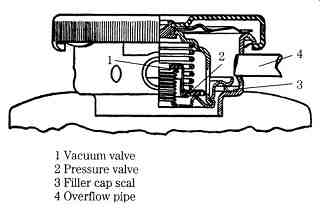
FIG. 13 Cutaway view of a pressure cap. GM Bedford Diesel
Fans
Fans for stationary applications operate continuously with power transmitted by one or more v-belts from the engine crankshaft. At 35 mph or so, road-going vehicles generate enough ram air velocity to dispense with the fan. Most passenger cars and light trucks use electric fans that cycle on and off in response to radiator header-tank temperature. Some earlier vehicles employed belt-driven fans with viscous clutches that used silicone as the working fluid. Clutch action was less than positive, allowing the fan to turn at 700-1000 rpm when it should have been disengaged. And when fully engaged, the clutch slipped, reducing fan speed by about 5%. Belt-driven on/off fans represent more recent thinking. Fans for light trucks employ electromagnetic clutches, similar to those used on air-conditioning compressors. Pneumatic clutches are favored for larger trucks with air brakes. The engine control unit (ECU) controls fan's on-off time in response to coolant temperature and other variables.
Table 2. Recommended v-belt tension* Belt width Tension
The primary maintenance requirement for belt-driven fans is to periodically check belt tension with a Borroughs or equivalent gauge ( Table 2). You can get a rough idea of tension by applying thumb pressure to the longest belt run between pulleys. A half-inch of "give" is about right, but err on the loose side since belts are less expensive than bearings. Examine belts for oil damage, heat checking, and wear.
Severe belt or pulley wear causes the belts to ride on the bottom of the pulley grooves. Paired belts should be replaced as a set: the stretch of the worn belt cannot be adjusted for without over-tensioning the replacement.
Check bearings by removing the belts and turning driven components by hand.
"Hard spots" or perceptible side play means that the associated bearing should be replaced. Viscous-clutch units sometimes fail to reach speed as they age. The only way this fault can be detected is to measure airflow velocity with a Caterpillar 8T-2700 or equivalent tool.
There is little that can be done to improve the performance of clutched fans, which have been, or should have been, engineered for the application. But fixed speed fans can often benefit for creative tinkering. Modifications include:
• Removing restrictions to air flow in front of the radiator and aft of the fan.
• Substituting a venturi-type shroud for the box shroud fitted to many industrial engines. Blade tips should come within 0.5 in. or less of the shroud.
• Increasing the radiator area swept by the fan. This can be done by specifying a larger diameter fan and, on suction fans, by displacing the fan at least on blade width behind the radiator.
• Investing in a high-efficiency fan and adjusting the drive ratio to turn it at the recommended blade-tip velocity.
Thermostats
A thermostat is a heat-sensitive valve that opens to admit coolant to the radiator when the temperature of coolant in the cylinder head reaches a predetermined temperature. Most thermostats open at 190 deg. F (87.8 deg. C).
FIG. 14 shows a wax-pellet thermostat in the closed and open positions.
When closed, a small amount of coolant passes through a bleed port to the radiator, but most returns to the pump through the bypass valve (8 in the drawing). As the coolant warms, the wax pellet (6) liquefies and expands to open the valve (2) to the radiator. Action is progressive. In the partially open position, coolant flow splits between the bypass valve and the radiator. At full open, all flow goes to the radiator. As the engine warms, radiator header-tank and cylinder temperatures should equalize.
Brass frames tend to break, and the metal bellows (rather than the telescoping tubes shown in the drawing) develop cracks. To check temperature response, heat the thermostat in water, supporting it away from the metal sides of the container (Fig. 15). The temperature rating, almost always stamped on the frame, refers to the temperature at which the thermostat cracks open. Raise the water temperature to about 25 deg. F (15 deg. C) above the temperature rating, adding antifreeze as necessary to prevent boiling. Ten minutes should be enough time for the unit to open fully.
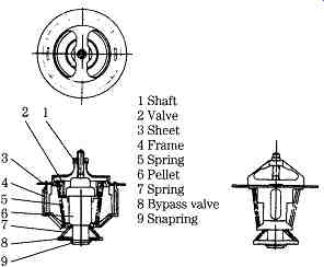
FIG. 14 Pill-type thermostat. Marine Engine Div. Chrysler Corp.
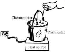
FIG. 15 Testing a thermostat. International

FIG. 16 Typical water pump. Marine Engine Div., Chrysler
Water pumps
As shown in Fig. 16, the water pump consists of a cast-iron or aluminum body, bearing assembly, ceramic face seal, shaft, and pressed-on impeller. Light duty pumps employ prelubricated bearings; the better types are plumbed into the engine oiling circuit. All have a bleed port outboard of the seal on the underside of the body casting. The port must remain open to provide an escape route for coolant that gets past seal faces and, on pressure-lubricated pumps, to prevent coolant contamination of the lube oil.

FIG. 17 Perkins rebuild kit. Most manufactures can supply the seal separately.
Pump failure is signaled by:
• Leaks from the bleed port. Some moisture is normal, but coolant streaks in this area mean seal and possible bearing failure.
• Perceptible side play or "hard spots" as the shaft is turned by hand. In severe cases, bearing wear allows the impeller to make rubbing contact with the pump body.
• Low pressure. Some engines have test ports on the inlet and outlet sides of the pump so that the pressure rise-usually in the order of 12 psi-can be measured. In the absence of these ports, about all one can do is intuit pump performance from the volume of coolant going into the radiator.
Water pumps for non-passenger car applications have factory support in the form of replacement seals and rebuild kits (Fig. 12-17). Most pumps require the use of an arbor press to remove and install the impeller and bearing pack.
Raw-water pumps assist the engine water pump in marine applications and in applications with remotely mounted radiators. The Jabsco unit in Fig. 18 employs prelubricated bearings and a mechanical face seal. The symmetrical impeller enables the pump to be driven in either direction by the expedient of swapping inlet and outlet port connections. Some models include a drain cock; for the unit illustrated, cover screws must be loosened in preparation for freezing temperatures.
To disassemble, remove the cover-retaining screws, end cover (2), and impeller (5). If the pump has much time on it, the impeller will be stuck. Remove it with a suitable puller or by spreading plier jaws under the impeller and tapping the shaft with a brass drift. Remove the cam screw and the cam (6). Replace the wear plate (7) as a precautionary measure.
Support the pump body in a vise and loosen the pinch bolt (24) that secures the body to the bearing housing (15). Remove the slinger (14) and pry off the inner seal from the pump body casting. Press the shaft (25) and bearings out of the casting.
Working from the impeller side, drive out the inner seal. All that remains is to separate the bearing pack from the shaft by removing the circlip (8).
Hoses
Hose condition is best checked by feel. Replace hoses that feel soft after the engine has shut down and pressure in the system has dissipated. A loose inner liner on the lower radiator hose creates an overheating problem that is nearly impossible to diagnose without removing the hose for inspection. Change all hoses every three years or 4000 hours. Close heater-hose valves during summer months to reduce the potential for leaks.
Most mechanics prefer to use stainless-steel clamps with a worm gear that engages serrations on the ribbon. It is doubtful whether these clamps provide more security than OEM types. Whatever style of clamp is used, avoid over-tightening. The clamp should compress the hose sheathing and not cut into it.

FIG. 18 Jabsco raw-water pump. GM Bedford Diesel
Accessories
As mentioned previously, cooling systems may incorporate turbo aftercoolers, oil coolers, and various other heat exchangers. Design variations make generalizations difficult. Most of these devices, such as the seawater aftercooler shown in Fig. 19, can be disassembled for cleaning and, with the proper fixtures, pressurized to detect leaks.

FIG. 19 Yanmar aftercooler uses seawater as the medium of heat transfer.
Prev. | Next
Home top
of page Similar articles