Most small diesel engines are fitted with an electric starter, battery, and generator.
The circuit might include glow plugs for cold starting and electrically operated instruments such as pyrometers and flow meters. The diesel technician should have knowledge of electricity.
This knowledge cannot be gleaned from the hardware just looking at an alternator will not tell you much about its workings. The only way to become even remotely competent in electrical work is to have some knowledge of basic theory.
This section is a brief, almost entirely nonmathematical, discussion of the theory.
Electrons
Atoms are the building blocks of all matter. These atoms are widely distributed; if we enlarged the scale to make atoms the size of pinheads, there would be approximately one atom per cubic yard of nothingness. But as tiny and as few as they are, atoms (or molecules, which are atoms in combination) are responsible for the characteristics of matter. The density of a substance, its chemical stability, thermal and electrical conductivity, color, hardness, and all its other characteristics are fixed by the atomic structure.
The atom is composed of numerous subatomic particles. Using high-energy disintegration techniques, scientists are discovering new particles almost on an annual basis. Some are reverse images of the others; some exist for only a few millionths of a second. But, we are only interested in the relatively gross particles whose behavior has been reasonably well understood for generations.
In broad terms the atom consists of a nucleus and one or more electrons in orbit around it. The nucleus has at least one positively charged proton and might have one or more electrically neutral neutrons. These particles make up most of the atom's mass. The orbiting electrons have a negative charge. All electrons, as far as we know, are identical. All have the same electrical potency. Their orbits are balanced by centripetal force and the pull of the positive charge of the nucleus ( FIG. 1).
A fundamental electrical law states unlike charges attract, like charges repel.
Thus two electrons, both carrying negative charges, repel each other. Attraction between opposites and the repulsion of likes are the forces that drive electrons through circuits.
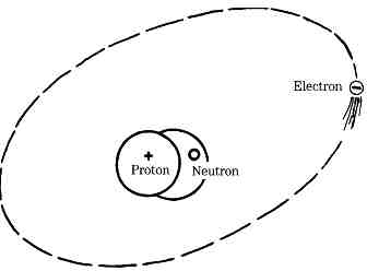
FIG. 1 Representation of an electron orbiting around a nucleus consisting of
a proton and a neutron.
Circuits
The term circuit comes from a Latin root meaning circle. It is descriptive because the path of electrons through a conductor is always in the form of a closed loop, bringing them back where they started.
A battery or generator has two terminals, or posts. One terminal is negative. It has a surplus of electrons available. The other terminal has a relative scarcity of electrons and is positive.
A circuit is a pathway between negative and positive terminals. The relative ease with which the electrons move along the circuit is determined by several factors.
One of the most Important is the nature of the conductor. Some materials are better conductors than others. Silver is at the top of the list, followed by copper, aluminum, iron, and lead. These and other conductors stand in contrast to that class of materials known as insulators. Most gases, including air, wood, rubber, and other organic materials, most plastics, mica, and slate are insulators of varying effectiveness.
Another class of materials is known as semiconductors. They share the characteristics-of both conductors and insulators and under the right conditions can act as either. Silicon and germanium semiconductors are used to convert alternating current (AC) to direct current (DC) at the alternator and to limit current and voltage outputs. These devices are discussed in more detail later in this section.
The ability of materials to pass electrons depends on their atomic structures.
Electrons flood into the circuit from the negative pole. They encounter other electrons already in orbit. The newcomers displace the orbiting electrons (like repels like) toward the positive terminal and, in turn, are captured by the positive charge on the nucleus (unlike attracts). This game of musical chairs continues until the circuit is broken or until the voltages on the terminals equalize. Gold, copper, and other conductors give up their captive electrons with a minimum of fuss. Insulators hold their electrons tightly in orbit and resist the flow of current.
You should not have the impression that electrons flow through various sub stances in a go/no-go manner. All known materials have some reluctance to give up their orbiting electrons. This reluctance is lessened by extreme cold, but never reaches zero. And all insulators 'leak' to some degree. A few vagrant electrons will pass through the heaviest, most inert insulation. In most cases the leakage is too small to be significant. But it exists and can be accelerated by moisture saturation and by chemical changes in the insulator.
Circuit characteristics
Circuits, from the simplest to the most convoluted, share these characteristics:
• Electrons move from the negative to the positive terminal. Actually the direction of electron movement makes little difference. In fact, for many years it was thought that electrons moved in the opposite direction-from positive to negative.
• The circuit must be complete and unbroken for electrons to flow. An incomplete circuit is described as open. The circuit might be opened deliberately by the action of a switch or a fuse, or it might open of its own accord as in the case of a loose connection or a broken wire. Because circuits must have some rationale besides the movement of electrons from one pole to the other, they have loads, which convert electron movement into heat, light, magnetic flux, or some other useful quantity. These working elements of the circuit are also known as sinks. They absorb, or sink, energy and are distinguished from the sources (battery and the generator). A circuit in which the load is bypassed is described as shorted. Electrons take the easiest, least resistive path to the positive terminal.
• Circuits can feed single or multiple loads. The arrangement of the loads determines the circuit type.
Series and parallel circuits
A series circuit has its loads connected one after the other like beads on a string ( FIG. 2A). There is only one path for the electrons between the negative and positive terminals. In a string of Christmas tree lights, each lamp is rated at 10V; 11 in. series required 110V. If any lamp failed, the string went dark.
Pure series circuits are rare today. (They can still be found as filament circuits in some AC/DC radios and in high-voltage applications such as airport runway lights.) But switches, rheostats, relays, fuses, and other circuit controls are necessarily in series with the loads they control.
Parallel circuits have the loads arranged like the rungs of a ladder, to provide multiple paths for current ( FIG. 2). When loads are connected in parallel, we say they are shunt. Circuits associated with diesel engines usually consist of parallel loads and series control elements. The major advantage of the parallel arrangement from a serviceman's point of view is that a single load can open without affecting the other loads. A second advantage is that the voltage remains constant throughout the network.
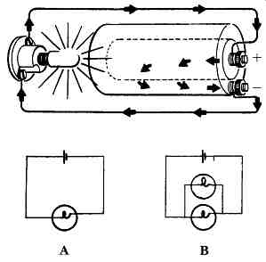
FIG. 2 Basic series circuit (top) and its schematic (A). In B, a second lamp
has been added with the first.
Single- and two-wire circuits
However the circuit is arranged-series, parallel, or in some combination of both-it must form a complete path between the positive and negative terminals of the source. This requirement does not mean the conductor must be composed entirely of electrical wire. The engine block, transmission, and mounting frame are not the best conductors from the point of view of their atomic structures. But because of their vast cross-sectional area, these components have almost zero resistance.
In the single-wire system the battery is grounded, or as the British say, earthed ( FIG. 3). These terms seem to have originated from the power station practice of using the earth as a return. With the exception of some Lucas and CAV systems, most modem designs have the negative post grounded. The 'hot' cable connects the positive post to the individual loads, which are grounded. Electrons flow from the negative terminal, through the loads, and back to the battery via the wiring.
The single-wire approach combines the virtues of simplicity and economy. But it has drawbacks. Perhaps the most consequential is the tendency for the connections to develop high resistances. One would think that a heavy strap bolted to the block would offer little resistance. Unfortunately this is not the case. A thin film of oil, rust, or a loose connection is enough to block the flow of current.
Corrosion problems are made more serious by weather exposure and electrolysis.
Electrolysis is the same phenomenon as occurs during electroplating. When current passes through two dissimilar metals (e.g., copper and cast iron) in the presence of damp air, one of the metals tends to disintegrate. In the process it undergoes chemical changes that makes it a very poor conductor.
Another disadvantage of the single-wire system, and the reason it is not used indiscriminately on aircraft and ocean-going vessels, is the danger of short circuits.
Contact between an uninsulated hot wire and the ground will shunt the loads down circuit.
The two-wire system (one wire to the load, and a second wire from it to the positive terminal) is preferred for critical loads and can be used in conjunction with a grounded system. Electrolytic action is almost nil, and shorts occur only in the unlikely event that two bare wires touch.
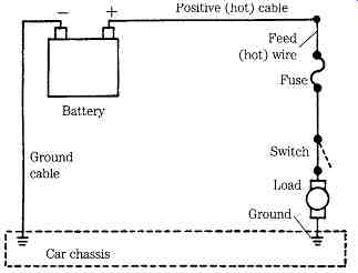
FIG. 3 The principle of grounding.
Electrical measurements
Voltage is a measure of electrical pressure. In many respects, it is analogous to hydraulic pressure. The unit of voltage is the volt, abbreviated V. Thus we speak of a 12-V or 24-V system. Prefixes, keyed to the decimal system, expand the terms so we do not need to contend with a series of zeros. The prefix K stands for kilo, or 1000. A 50-kV powerline delivers 50,000V. At the other end of the scale, milli means 1/ 1000, and one millivolt (1 mV) is a thousandth of a volt.
The ampere, shortened sometimes to amp and abbreviated A is a measure of the quantity of electrons flowing past a given point in the circuit per second. One ampere represents the flow of 6.25 _ 1018 electrons per second. Amperage is also referred to as current intensity or quantity. From the point of view of the loads on the circuit, the amperage is the draw. A free-running starter motor might draw 100A, and three times as much under cranking loads.
Resistance is measured in units named after G. S. Ohm. Ohms are expressed by the last letter of the Greek alphabet, omega (Ω). Thus we might speak of a 200Ω resistance.
The resistance of a circuit determines the amount of current that flows for a given applied voltage. The resistance depends on the atomic structure of the conductor-how tightly the electrons are held captive in their orbits-and on certain physical characteristics. The broader the cross-sectional area of the conductor, the lesser opposition to the current. And the longer the path formed by the circuit between the poles of the voltage source, the more is the resistance. Think of these two dimensions in terms of ordinary plumbing. The resistance to the flow of a liquid in a pipe is inversely related to its diameter (decreases as diameter increases) and directly related to its length. Resistance in the pipe produces heat, exactly as does resistance in an electrical conductor.
Resistance is generally thought of as the electrical equivalent of friction-a kind of excise tax that we must pay to have electron movement. There are, however, positive uses of resistance. Resistive elements can be deliberately introduced in the circuit to reduce current in order to protect delicate components. The heating effect of resistance is used in soldering guns and irons and in the glow plugs employed as starting aids in diesel engines.
Ohm's law
The fundamental law of simple circuits was expressed by the Frenchman G. S. Ohm in the early 1800s in a paper on the effects of heat on resistance. The law takes three algebraic forms, each based on the following relationship: a potential of 1V drives 1A through a resistance of 1_. In the equations the symbol E stands for electromotive force, or, as we now say, volts. An I represents intensity, or current, and R is resistance in ohms.
The basic relationship is expressed as:
This form of the equation states that current in amperes equals voltage in volts divided by resistance in ohms. If a circuit with a resistance of 6 ohm, is connected across a 12V source, the current is 2A (12/6 = 2). Double the voltage (or halve the resistance), and the current doubles. FIG. 4 shows this linear (straight-line graph) relationship.
Another form of Ohm's law is ...... or resistance equals voltage divided by current. The 12V potential of our hypothetical circuit delivers 2A, which means the resistance is 6 ohm. The relationship between amperage and resistance with a constant voltage is illustrated in FIG. 5.
Another way of expressing Ohm's law is E=IR or voltage equals current multiplied by resistance. Two amperes through 6 ohm requires a potential of 12V. Double the resistance, and twice the voltage is required to deliver the same amount of current ( FIG. 6).
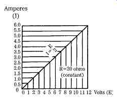
FIG. 4 Relation between amperage and voltage, resistance constant.
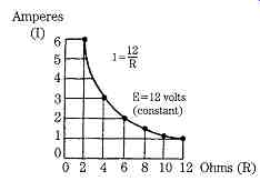
FIG. 5 Relation between amperage and resistance, voltage constant.
Various memory aids have been devised to help students remember Ohm's law.
One involves an Indian, an eagle, and a rabbit. The Indian (I ) sees the eagle (E ) flying over the rabbit (R); this gives the relationship I = E/R. The eagle sees both the Indian and the rabbit in the same level, or E= IR. And the rabbit sees the eagle over the Indian, or R = E/I. A visual aid is shown in FIG. 7. The circle is divided into three segments. To determine which form of the equation to use, put your finger on the quantity you want to solve for.
All of this might seem academic, and in truth, few mechanics perform calculations with Ohm's law. It is usually easier to measure all values directly with a meter.
Still, it is very important to have an understanding of Ohm's law. It is the best description of simple circuits we have.
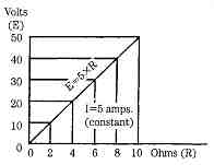
FIG. 6 Relation between voltage and resistance, amperage constant.

FIG. 7 Ohm's law: Cover the unknown with your finger to determine which of the
three equations to use.
For example, suppose the wiring is shorted: electrons have found a more direct (shorter) path to the positive terminal of the battery. Ohm's law tells us certain facts about the nature of shorts, which are useful in troubleshooting. First, a short increases the current in the affected circuit, because current values respond inversely to resistance. This increase will generate heat in the conductor and might even carbonize the insulation. Voltage readings will be low because the short has almost zero resistance. Now suppose we have a partially open circuit caused by a corroded terminal. The current through the terminal will be reduced, which means that the lights or whatever other load is on the circuit will operate at less-than-peak output. The terminal will be warm to the touch, because current is transformed to heat by the presence of resistance. Voltage readings from the terminal to ground will be high on the source side of the resistance and lower than normal past the bottleneck.
Direct and alternating current
Diesel engines might employ direct or alternating currents. The action of direct, or unidirectional, current can be visualized with the aid of the top drawing in FIG. 8.
Alternating current is expressed by the opposed arrows in the lower drawing. Flow is from the negative to the positive poles of the voltage source, but the poles exchange identities, causing the current reversal. The positive becomes negative, and the negative becomes positive.
The graph in FIG. 9 represents the rise, fall, and reversal of alternating current.
Because the amplitude changes over time, alternating voltage and current values require some qualification. The next drawing illustrates the three values most often used.
Peak-to-peak values refer to the maximum amplitude of the voltage and amperage outputs in both directions. In FIG. 10 the peak-to-peak value is 200 Vp-p (or 200 Ap-p). The half-cycle (alternation) on top of the zero reference line is considered to be positive; below the line alternation is negative.

FIG. 8 Direct and alternating current.
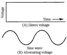
FIG. 9 Direct- and alternating current waveforms.
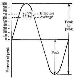
FIG. 10 Various valves used to indicate sine-wave amplitude.
The average, or mean, value represents an average of all readings. In FIG. 10 it is 63.7 units.
The root mean square (rms) value is sometimes known as the effective value.
One rms ampere has the same potential for work as 1-A direct current. Unless otherwise specified, alternating current values are rms (effective) values and are directly comparable to direct current in terms of the work they can do. Standard meters are equipped with appropriate scales to give rms readings.
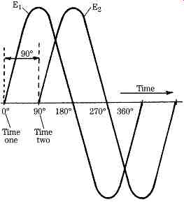
FIG. 11 Voltage sine waves 90° apart.
The illustration depicts one complete cycle of alternating current. The number of cycles completed per second is the frequency of the current. One cycle per second is the same as one hertz (1 Hz). Domestic household current is generated at 60 Hz.
The alternating current generators used with diesel engines are variable-frequency devices because they are driven by the engine crankshaft. At high speed a typical diesel alternating current generator will produce 500-600 Hz.
In addition to these special characteristics, alternating current outputs can be superimposed upon each other (see FIG. 11). The horizontal axis (X-axis) represents zero output-it is the crossover point where alternations reverse direction. In this particular alternator 360° of rotation of the armature represents a complete out put cycle from maximum positive to maximum negative and back to maximum positive. The X-axis can be calibrated in degrees or units of time (assuming that the alternator operates at a fixed rpm). Note that there are two sine waves shown. These waves are out of phase; E1 leads E2 by 90° of alternator rotation. Alternators used on diesel installations usually generate three output waves 120° apart. Multiphase outputs are smoother than single-phase outputs and give engineers the opportunity to build multiple charging circuits into the alternator. Circuit redundancy gives some assurance against total failure; should one charging loop fail, the two others continue to function.
Magnetism
Electricity and magnetism are distinct phenomena, but related in the sense that one can be converted into the other. Magnetism can be employed to generate electricity, and electricity can be used to produce motion through magnetic attraction and repulsion.
The earth is a giant magnet with magnetic poles located near the geographic poles ( FIG. 12). Magnetic fields extend between the poles over the surface of the earth and through its core. The field consists of lines of force, or flux. These lines of force have certain characteristics, which, although they do not fully explain the phenomenon, at least allow us to predict its behavior. The lines are said to move from the north to the south magnetic pole just as electrons move from a negative to a positive electrical pole. Magnetic lines of force make closed loops, circling around and through the magnet. The poles are the interface between the internal and external paths of the lines of force. When encountering a foreign body, the lines of force tend to stretch and snap back upon themselves like rubber bands. This characteristic is important in the operation of generators.
Lines of force penetrate every known substance, as well as the emptiness of outer space. However, they can be deflected by soft iron. This material attracts and focuses flux in a manner analogous to the action of a lens on light. Lines of force 'prefer' to travel through iron, and they digress to take advantage of the permeability (magnetic conductivity) of iron ( FIG. 13).
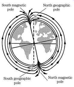
FIG. 12 Earth's magnetic field.
The permeability of iron is exploited in almost all magnetic machines.
Generators, motors, coils, and electromagnets all have iron cores to direct the lines of force most efficiently.
When free to pivot, a magnet aligns itself with a magnetic field, as shown in FIG. 14. Unlike magnetic poles attract, like magnetic poles repel. The south magnetic pole of the small magnet (compass needle) points to the north magnetic pole of the large bar magnet.
Electromagnets
Electromagnets use electricity to produce a magnetic field. Electromagnets are used in starter solenoids, relays, and voltage-and current-limiting devices. The principle upon which these magnets operate was first enunciated by the Danish researcher Hans Christian Oersted. In 1820, he reported a rather puzzling phenomenon: A compass needle when placed near a conductor, deflected as the circuit was made and broken. Subsequently it was shown that the needle reacted because of the presence of a magnetic field at right angles to the conductor. The field exists as long as current flows, and its intensity is directly proportional to the amperage.
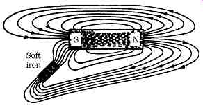
FIG. 13 Effects of soft iron on a magnetic field.
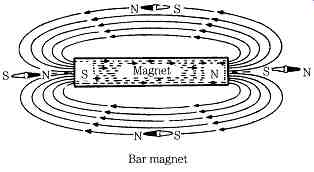
FIG. 14 Compass deflections in a magnetic field.
The field around a single strand of conductor is too weak to have practical application. But if the conductor is wound into a coil, the weak fields of the turns rein force each other (Fig- 10-15). Further reinforcement can be obtained by inserting an iron bar inside the coil to give focus to the lines of force. The strength of the electromagnet depends on the number of turns of the conductor, the length/width ratio of the coil, the current strength, and the permeability of the core material.
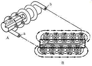
FIG. 15 Electromagnet construction showing how magnetic fields mutually reinforce
one another.
Voltage sources
Starting and charging systems employ two voltage sources. The generator is electromagnetic in nature and is the primary source. The battery, which is electro chemical in nature, is carried primarily for starting. Also, in case of overloads, the battery can send energy into the circuit.
Generator principles
In 1831 Michael Faraday reported that he had induced electricity in a conductor by means of magnetic action. His apparatus consisted of two coils, wound over each other but not electrically connected. When he made and broke the circuit to one coil, momentary bursts of current were induced in the second. Then Faraday wound the coils over a metal bar and observed a large jump in induced voltage. Finally he reproduced the experiment with a permanent magnet. Moving a conductor across a magnetic field produced voltage. The intensity of the voltage, depended on the strength of the field, the rapidity of movement, and the angle of movement. His generator was most efficient when the conductor cut the lines of force at right angles.
The rubber band effect mentioned earlier helps one to visualize what happens when current is induced in the conductor. A secondary magnetic field is set up, which resists the movement of the conductor through the primary field. The greater the amount of induced current, the greater the resistance, and the more power required to overcome it.
Alternator
FIG. 16 illustrates Faraday's apparatus. Note that there must be relative movement between the magnetic field and conductor. Either can be fixed as long as one can move. Note also that the direction of current is determined by the direction of movement. Of course, this shuttle generator is hardly efficient; the magnet or conductor must be accelerated, stopped, and reversed during each cycle.
The next step was to convert Faraday's laboratory model to rotary motion ( FIG. 17). The output alternates with the position of the armature relative to the fixed magnets. In FIG. 17A the windings are parallel to the lines of force and the output is zero. Ninety degrees later the output reaches its highest value because the armature windings are at right angles to the field. At 180° of rotation (C) the output is again zero. This position coincides with a polarity shift. For the remainder of the cycle, the movement of the windings relative to the field is reversed.
To determine the direction of current flow from a generator armature, position the left hand so that the thumb points in the direction of current movement and the forefinger points in the direction of magnetic flux (from the north to the south pole).
Extend the middle finger 90° from the forefinger; it will point to the direction of cur rent. As convoluted as the left-hand rule for generators sounds, it testifies to the fact that polarity shifts every 180° of armature rotation. This is true of all dynamos, whether the machine is DC generator or AC generator (alternator).

FIG. 16 Voltage produced by magnetism.

FIG. 17 Alternating current generator (or alternator).
The frequency in hertz depends on the rotational speed of the armature and on the number of magnetic poles. FIG. 18 illustrates a four-pole (two-magnet) alternator, which for a given rpm, has twice the frequency of the single-pole machine in the previous illustration. Normally, alternators supplied for diesel engines have four magnetic poles and are designed to peak at 6000 rpm. Their frequency is given by:
...where f is frequency in hertz and P is the number of poles. Thus, at 6000 rpm, a typical alternator should deliver current at a frequency of 2000 Hz.
The alternators depicted in Figs. 10-17 and 10-18 are simplifications. Actual alternators differ from these drawings in two important ways. First, the fields are not fixed, but rotate as part of an assembly called the rotor. Secondly, the fields are not permanent magnets; instead they are electromagnets whose strength is controlled by the voltage regulator. Electrical connection to the rotor is made by a pair of brushes and slip rings.
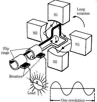
FIG. 18 Four-pole alternator.
DC generator
Direct-current (DC) generators develop an alternating current (AC) that is mechanically rectified by the commutator-brush assembly. The commutator is a split copper ring with the segments insulated from each other. The brushes are carbon bars that are spring-loaded to bear against the commutator. The output is pulsating direct current, as shown in FIG. 19. The pulse frequency depends on the number of armature loops, field poles, and rpm. A typical generator has 24-28 armature loops and 4 poles. The fields are electromagnets and are energized by 8-12% of the generator output cur rent. The exact amount of current detailed for this excitation depends on the regulator, which in turn, responds to the load and state of charge of the generator. A few surviving generators achieve output regulation by means of a third brush.
Third-brush generator
The third brush is connected to the field coils as shown in FIG. 20. At low rotational speeds the magnetic lines of force bisect the armature in a uniform manner.
But as speed and output increase, the field distorts. The armature generates its own field, because a magnetic field is created at right angles to a conductor when current flows through it. The resulting field distortion, sometimes called magnetic whirl, places the loops feeding the third brush in an area of relative magnetic weakness.
Consequently, less current is generated in these loops, and the output to the fields is lessened. The fields become correspondingly weak, and the total generator output as defined by the negative and positive brushes remains stable or declines.
The output depends on the position of the third brush, which can be moved in or out of the distorted field to adjust output for anticipated loads. Moving the brush in the direction of armature rotation increases the output; moving it against the direction of rotation reduces the output. When operated independently from the external circuit, the brushes must be grounded to protect the windings. Many of these generators have a fuse in series with the fields.
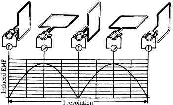
FIG. 19 Single-loop direct current generator.
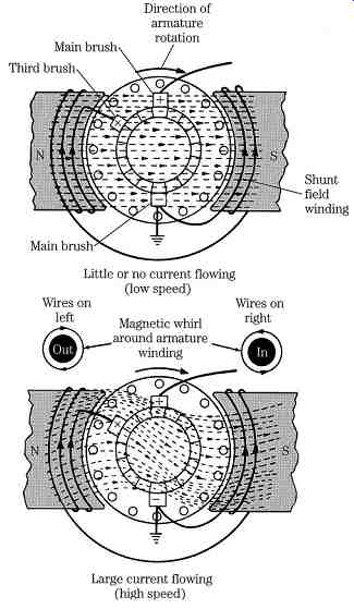
FIG. 20 Third-brush generator. A speed and output increase, the field's excitation
current drops because of magnetic whirl.
DC motors
One of the peculiarities of a direct current generator is that it will 'motor' if the brushes are connected to a voltage source. In like manner a direct current motor will "gen" if the armature is rotated by some mechanical means. Some manufacturers of small-engine accessories have taken advantage of this phenomenon to combine both functions in a single housing. One such system is the Dynastart system employed on many single-cylinder Hatz engines (shown schematically in FIG. 21).
FIG. 22 illustrates the motor effect. In the top sketch the conductor is assumed to carry an electric current toward you. The magnetic flux around it travels in a clockwise direction. Magnetic lines of force above the conductor are distorted and stretched. Because the lines of force have a strong elastic tendency to shorten, they push against the conductor. Placing a loop of wire in the field (bottom sketch) instead of a single conductor doubles the motor effect. Current goes in the right half of the loop and leaves at the left. The interaction of the fields causes the loop (or, collectively, the armature) to turn counterclockwise. Reversing the direction of the current would cause torque to be developed in a clockwise direction.

FIG. 21 Combination generator and starter motor. Teledyne Wisconsin Motor
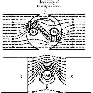
FIG. 22 Motor effect created by current bearing conductor in a magnetic field.
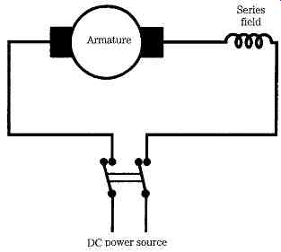
FIG. 23 Series field and armature connections typical of starter motors.
Starter motors are normally wired with the field coils in series with the armature ( FIG. 23). Any additional load added to a series motor will cause more current in the armature and correspondingly more torque. Because this increased current must pass through the series field, there will be a greater flux. Speed changes rapidly with load. When the rotational speed is low, the motor produces its maximum torque.
A starter might draw 300A during cranking, more than twice that figure at stall.
Storage batteries
Storage batteries accumulate electrical energy and release it on demand. The familiar lead-acid battery was invented more than 100 years ago by Gaston Plante.
It suffers from poor energy density (watt-hours per pound) and poor power density (watts per pound). The average life is said to be in the neighborhood of 360 complete charge-discharge cycles. During charging, the lead-acid battery shows an efficiency of about 75%; that is, only three-quarters of the input can be retrieved.
Yet it remains the only practical alternative for automotive, marine, and most stationary engine applications. Sodium-sulfur, zinc-air, lithium-halide, and lithium chlorine batteries all have superior performance, but are impractical by reason of cost and, in some cases, the need for complex support systems.
The lead-acid battery consists of a number of cells (hence the name battery) connected in series. Each fully charged cell is capable of producing 2.2V. The number of cells fixes the output; 12V batteries have six cells; 24V batteries have 12. The cells are enclosed in individual compartments in a rubberoid or (currently) high-impact plastic case. The compartments are sealed from each other and, with the exception of Delco and other "zero maintenance" types, open to the atmosphere. The lower walls of the individual compartments extend below the plates to form a sediment trap. Filler plugs are located on the cover and can be combined with wells or other visual indicators to monitor the electrolyte level.
The cells consist of a series of lead plates ( FIG. 24) connected by internal straps. Until recently the straps were routed over the top of the case, making convenient test points for the technician. Unfortunately, these straps leaked current and were responsible for the high self-discharge rates of these batteries.
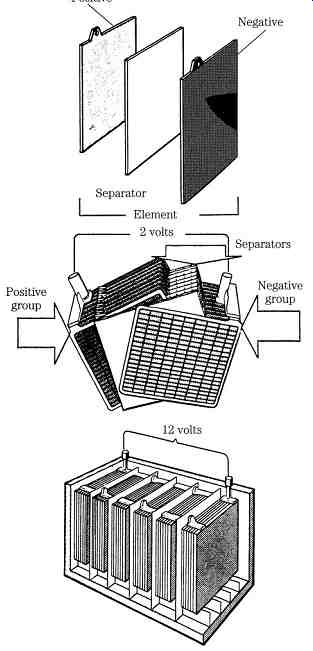
FIG. 24 Lead-acid storage battery construction.
The plates are divided into positive and negative groups and separated by means of plastic or fiberglass sheeting. Some very large batteries, which are built almost entirely by hand, continue to use fir or Port Orford cedar separators. A few batteries intended for vehicular service feature a loosely woven fiberglass padding between the separators and positive plates. The padding gives support to the lead filling and reduces damage caused by vibration and shock.
Both sets of plates are made of lead. The positive plates consist of a lead grid work that has been filled with lead oxide paste. The grid is stiffened with a trace of antimony. Negative plates are cast in sponge lead. The plates and separators are immersed in a solution of sulfuric acid and distilled water. The standard proportion is 32% acid by weight.
The level of the electrolyte drops in use because of evaporation and hydrogen loss. (Sealed batteries have vapor condensation traps molded into the roof of the cells.) It must be periodically replenished with distilled water. Nearly all storage batteries are shelved dry, and filled upon sale. Once the plates are wetted, electrical energy is stored in the form of chemical bonds.
When a cell is fully charged the negative plates consist of pure sponge lead (Pb in chemical notation), and the positive plates are lead dioxide (PbO2, sometimes called lead peroxide). The electrolyte consists of water (H2O) and sulfuric acid (H2SO4). The fully charged condition corresponds to drawing A in FIG. 25. During discharge both sponge lead and lead dioxide become lead sulfate (PbSO4). The percentage of water in the electrolyte increases because the SO4 radical splits off from the sulfuric acid to combine the plates. If it were possible to discharge a lead-acid battery completely, the electrolyte would be safe to drink. In practice, batteries cannot be completely discharged in the field. Even those that have sat in junkyards for years still have some charge.
During the charge cycle the reaction reverses. Lead sulfate is transformed back into lead and acid. However, some small quantity of lead sulfate remains in its crystalline form and resists breakdown. After many charge-discharge cycles, the residual sulfate permanently reduces the battery's output capability. The battery then is said to be sulfated.
The rate of self-discharge is variable and depends on ambient air temperature the cleanliness of the outside surfaces of the case, and humidity. In general it averages 1% a day. Batteries that have discharged below 70% of full charge might sulfate.
Sulfation becomes a certainty below the 70% mark. In addition to the possibility of damage to the plates, a low charge brings the freezing point of the electrolyte to near 32°F.
Temperature changes have a dramatic effect on the power density. Batteries are warm-blooded creatures and perform best at room temperatures. At 10°F the battery has only half of its rated power.
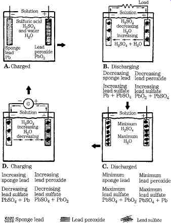
FIG. 25 Chemical action in a lead-add cell.
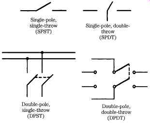
FIG. 26 Schematic symbols of commonly used switches.
Switches
Switches neither add energy to the circuit nor take it out. Their function is to give flexibility by making or breaking circuits or by providing alternate current paths.
They are classified by the number of poles (movable contacts) and throws (closed positions). FIG. 26 illustrates four standard switch types in schematic form.
A single-pole, single-throw switch is like an ordinary light switch in that it makes and breaks a single circuit with one movement from the rest position. Single-pole, double-throw (SPDT) switches have three terminals, but control a single circuit with each throw. As one is completed, the other is opened. You can visualize an SPDT as a pair of SPST switches in tandem. Double-pole, double-throw switches control two circuits with a single movement. Think of the DPDT as two DPST switches combined, but working so that when one closes the other opens.
Self-actuating switches
Not all switching functions are done by hand. Some are too critical to trust to the operator's alertness. In general two activating methods are used. The first depends on the effect of heat on a bimetallic strip or disc to open or close contacts.
Heat can be generated through electrical resistance or, as is more common, from, the engine coolant. The bimetallic element consists of two dissimilar metals bonded back-to-back. Because the coefficient of expansion is different for the metals, the strip or disc will deform inward, in the direction of the least expansive metal. FIG. 27 illustrates this in a flasher unit. Other switches operate by the pressure of a fluid acting against a diaphragm. The fluid can be air, lube oil, or brake fluid. The most common use of such switches is as oil pressure sensors ( FIG. 28).
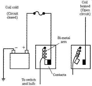
FIG. 27 Bimetallic switch operation.
Relays
Relays are electrically operated switches. They consist of an electromagnet, a movable armature, a return spring, and one or more contact sets. Small currents excite the coil, and the resulting magnetic field draws the armature against the coil. This linear movement closes or opens the contacts. The attractiveness of relays is that small currents-just enough to excite the electromagnet-can be used to switch large currents. You will find relays used to activate charging indicator lamps ( FIG. 29), some starter motors, horns, remotely controlled air trips, and the like.
Solenoids are functionally similar to relays. The distinction is that the movable armature has some nonelectrical chore, although it might operate switch contacts in the bargain. Many starter motors employ a solenoid to lever the pinion gear into engagement with the flywheel. The next section discusses several of these starters.
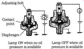
FIG. 28 Diaphragm switch (oil pressure).
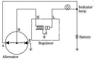
FIG. 29 Relay-tripped charging indicator lamp.
Circuit protective devices
Fuses and fusible links are designed to vaporize and open the circuit during overloads. Some circuits are routed through central fuse panels. Others can be protected by individual fuses spliced into the circuit at strategic points.
Fusible links are appearing with more frequency as a protection for the battery regulator circuit ( FIG. 30). Burnout is signaled by swollen or discolored insulation over the link. New links can be purchased in bulk for soldered joints, or in precut lengths for use with quick-disconnects. Before replacing the link, locate the cause of failure, which will be a massive short in the protected circuit.
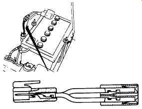
FIG. 30 Fusible link.
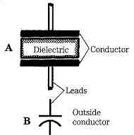
FIG. 31 Capacitor construction and schematic symbol.
On the other hand, a blown fuse is no cause for alarm. Fuses fatigue and become resistive with age. And even the best-regulated charting circuit is subject to voltage and current spikes, which can take out a fuse but otherwise are harmless.
Chronic failure means a short or a faulty regulator.
Capacitors (condensers) Two centuries ago it was thought that Leyden jars for storing charges actually condensed electrical "fluid." These glass jars, wrapped with foil on both the inner and outer surfaces, became known as condensers. The term lingers in the vocabulary of automotive and marine technicians, although capacitor is more descriptive of the devices' capacity for storing electricity.
A capacitor consists of two plates separated by an insulator or dielectric ( FIG. 31).
In most applications the plates and dielectric are wound on each other to save space.
A capacitor is a kind of storage tank for electrons. In function it is similar to an accumulator in hydraulic circuits. Electrons are attracted to the negative plate by the close proximity of the positive plate. Storing the electrons requires energy, which is released when the capacitor is allowed to discharge. Shorting the plates together sends free electrons out of the negative plate and to the positive side. There is a to and-fro shuttle of electrons between the plates until the number of electrons on the plates is equalized. The number of oscillations depends on circuit resistance and reactance (or the reluctance of the capacitor to charge because of the mutual repulsion of electrons on the negative plate).
Capacitors block direct current, but pass alternating current. The electrons do not physically penetrate the dielectric. The distortions in the orbits of the electrons in the dielectric displace or attract electrons at the plates. The effect on alternating current in a circuit is often as though the dielectric did not exist at least at the higher frequencies.
Capacitors are found at the generator or alternator, where they shunt high frequency alternating current to ground to muffle radio interference.
Solid-state components
Although the transistor was invented in the Bell Laboratories in 1947, it and its progeny remain a mystery to most mechanics. These components are used in all alternators to rectify alternating current to direct current and can be found in current regulators produced by CAV, Lucas, Bosch, and Delco. In the future they will have a much wider use and possibly will substitute for relays.
Solid-state components are made of materials called semiconductors, which fall midway in the resistance spectrum between conductors and insulators. In general these components remain nonconductive until subjected to a sufficient voltage.
Silicon and germanium are the most-used materials for semiconductors.
Semiconductor crystals for electronics are artificial crystals, grown under laboratory conditions. In the pure state these crystals are electrically just mediocre conductors.
But if minute quantities of impurities are added in the growth state, the crystals acquire special electrical characteristics that make them useful for electronic devices.
The process of adding impurities is known as doping.
When silicon or germanium, is doped with arsenic or phosphorus, the physical structure remains crystalline. But for each atom of impurity that combines with the intrinsic material, one free electron becomes available. This material has electrons to carry current and is known as n-type semiconductor material.
On the other hand the growing crystals might be doped with indium, aluminum, boron, or certain other materials and result in a shortage of electrons in the crystal structure. "Missing" electrons can be thought of as electrical holes in the structure of the crystal. These holes accept electrons that blunder by, but the related atom quickly releases the newcomer. When a voltage is applied to the semiconductor, the holes appear to drift through the structure as they are alternately filled and emptied.
Crystals with this characteristic are known as p-type materials, because the holes are positive charge carriers.
Diode operation
When p-type material is mated with n-type material, we have a diode. This device has the unique ability to pass current in one direction and block it in the other. When the diode is not under electrical stress, p-type holes in the p-material and electrons in the n-material complement each other at the interface of the two materials. This interface, or junction, is electrically neutral, and presents a barrier to the charge carriers. When we apply negative voltage to the n-type material, electrons are forced out of it. At the same time, holes in the p-type material migrate toward the direction of current flow. This convergence of charge carriers results in a steady current in the circuit connected to the diode. Applying a negative voltage to the n-type terminal so the diode will conduct is called forward biasing.
If we reverse the polarity-that is, apply positive voltage to the n-type material-electrons are attracted out of it. At the same time, holes move away from the junction on the p side. Because charge carriers are thus made to avoid the junction, no current will pass. The diode will behave as an insulator until the reverse bias voltage reaches a high enough level to destroy the crystal structure.
Diodes are used to convert alternating current from the generator to pulsating direct current. An alternator typically has three pairs of diodes mounted in heat sinks (heat absorbers).
Diodes do have some resistance to forward current and so must be protected from heat by means of shields and sinks. In a typical alternator the three pairs of diodes that convert alternating current to pulsating direct current are pressed into the aluminum frame. Heat generated in operation passes out to the whole generator.
Solid-state characteristics
As useful as solid-state components are, they nevertheless are subject to certain limitations. The failure mode is absolute. Either the device works or it doesn't. And in the event of failure, no amount of circuit juggling or tinkering will restore operation. The component must be replaced. Failure might be spontaneous-the result of manufacturing error compounded by the harsh environment under the hood-or it might be the result of faulty service procedures. Spontaneous failure usually occurs during the warranty period. Service-caused failures tend to increase with time and mileage as the opportunities for human error increase.
These factors are lethal to diodes and transistors High inverse voltage resulting from wrong polarity Jumper cables connected backward or a battery installed wrong will scramble the crystalline structure of these components.
Vibration and mechanical shock --Diodes must be installed in their heat sinks with the proper tools. A 2 _ 4 block is not adequate.
Short circuits-- Solid-state devices produce heat in normal operation. A transistor, for example, causes a 0.3-0.7V drop across the collector-emitter terminals. This drop, multiplied by the current, is the wattage consumed. Excessive current will overheat the device.
Soldering-- The standard practice is for alternator diodes to be soldered to the stator leads. Too much heat at the connection can destroy the diodes.
Prev. | Next
Home top
of page Similar articles