When power is first applied to the coil, the amount of current drawn by the coil to begin building the magnetic field will be approximately three times the amount of current that is used after the armature moves to the middle of the coil. Fig. 3 shows a diagram of the current flow pattern when a solenoid coil is energized. The initial current flow is called inrush current. The current that holds the armature in the energized position is called holding current.
If the coil is powered with DC voltage, an inductive voltage is created anytime power to the coil is de-energized. The inductive voltage is called an inductive kick and it is up to ten times the applied voltage and is in reverse polarity to the applied voltage. A diode or other type of suppression device must be connected across the coil of the solenoid to protect any other electronic components in the circuit that may be damaged by this voltage. The diode is connected in reverse bias across the DC solenoid coil so that when voltage is applied in normal polarity, the diode does not provide a path for current. When the solenoid coil is de-energized, the inductive voltage is the opposite polarity to the power supply, so it will flow through the diode and back into the coil. Since the coil is made of a large length of wire. the energy of the inductive voltage will be dissipated as it moves through the wire. This will render the excessive inductive voltage harmless. The fact that the inductive voltage will travel through the diode in the forward bias direction means the 0.7-1 volt drop across the diode junction will also limit the V=< (dv/dt) surge. Fig. 4 (below) illustrates an example of the diode connected across the coil of a solenoid that is powered with DC voltage.
Since the armature physically moves inside the coil when power is applied to the coil, it will change the magnetic field, which will cause the current to drop to the holding-current level. If the armature did not move, the current would remain at the inrush level, which exceeds the current rating for the wire. The coil would quickly overheat and the wire would be burned until it caused an open. The level of the inrush current is determined by dividing the applied voltage by the resistance of the wire in the coil. This means that you should never connect voltage to a coil if it is not mounted on an armature. Some technicians test the coil by trying to pull the coil off the armature to see if it is magnetized. A problem occurs if the coil is pulled too hard and actually comes off the armature because the current will increase to the inrush level and cause the coil that is being tested to burn out. If the coil is tested with voltage, it is important that the coil is mounted over the armature.
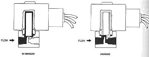
Fig. 1: (a) A solenoid valve that is in the de-energized position so that no fluid will flow through it. (b) A solenoid valve that is in the energized position so that fluid will flow through it.
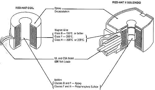
Fig. 2: Cut-away view of coils for solenoid valves.
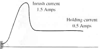
Fig. 3: A diagram of inrush and holding current for a solenoid coil.
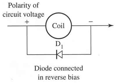
Fig. 4: A diode is connected in reverse bias across a solenoid coil that is powered by dc voltage. The diode protects other electronic components in the circuit from inductive voltage that occurs when dc voltage to the coil is de-energized.
Previous Article | Next Article: Typical Voltages and Wattages for Solenoid Valves
If you liked the "Solenoid Valves" article above, you may also be interested in the rest of the articles in our comprehensive series on: OUTPUT DEVICES
Or, browse through our categorical or master article archive to see a listing of all main topics.