AMAZON multi-meters discounts AMAZON oscilloscope discounts Circuit Testing is the testing of electric circuits to determine and locate any of the following circuit conditions:
- an open circuit
- a short circuit with another conductor in the same circuit
- a ground, which is a short circuit between a conductor and ground
- leakage (a high-resistance path across a portion of the circuit, to another circuit, or to ground)
- a cross (a short circuit or leakage between conductors of different circuits)
Circuit testing for complex systems often requires extensive automatic checkout gear to determine the faults defined above as well as many quantities other than resistance.
In cable testing, the first step in fault location is to identify the faulty conductor and type of fault. This is done with a continuity tester, such as a battery and flashlight bulb or buzzer (Fig. 1), or an ohmmeter.
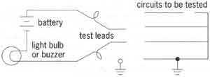
ABOVE: Fig.1.
Simple continuity test setup.
Useful for locating faults in relatively low-resistance circuits,
the Murray loop is shown in Fig. 2 with a ground fault in the circuit under
test. A known "good" conductor is joined to the faulty conductor at a convenient point beyond the
fault but at a known distance form the test connection. One terminal of
the test battery is grounded. The resulting Wheatstone bridge is then balanced
by adjusting RB until a null is obtained, as indicated by the detector
in Fig. 2. Ratio RA/RB is then known. For a circuit having a uniform ratio
of resistance with length, circuit resistance is directly proportional
to circuit length. Therefore, the distance to the fault is determined from
the producer given by Eqns. (1) - (3). From Eqn. (3) and a knowledge of
total length l of the circuit, once ratio r has been measured, the location
of the fault x is determined.
| RC ∝ l+(l-x) RD ∝ x | (1) |
| RA/RB = r = RC/RD = (2l - x)/x | (2) |
| x = 2l/(r - 1) | (3) |
ABOVE: Fig. 2. Murray loop for location of ground fault.
The Varley-loop test is similar to the Murray-loop test except for the inclusion of the adjustable resistance R. The Varley loop is used for fault location in high-resistance circuits.
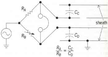
An alternating-current capacitance bridge can be used for locating an open circuit as shown in Fig. 3. One test terminal is connected to the open conductor and the other terminal to a conductor of known continuity in the cable. All conductors associated with the test are opened at a convenient point beyond audio oscillator supplies the voltage to the bridge, which is balanced by adjusting RB for a null as detected by the earphones. Measured ratio RA/RB equals the ratio of capacitances between the lines and the grounded sheath. Because each capacitance is proportional to the length of line connected to the bridge, the location of the open circuit can be determined from Eqn. (4).
ABOVE: Fig. 3. Alternating-current capacitance bridge used in location
of an open circuit in one conductor.
| RA/RB = CC/CD | (4) |